Nissan Altima (L32) 2007-2012 Service Manual: Key slot illumination
Description
Blinks when Intelligent Key insertion is required.
Component Function Check

Check key slot illumination (“KEY SLOT ILLUMI”) Active Test mode.
Is the inspection result normal? YES >> Key slot function is OK.
NO >> Refer to SEC-114, "Diagnosis Procedure".
Diagnosis Procedure
1.CHECK KEY SLOT ILLUMINATION OUTPUT SIGNAL
Check voltage between key slot connector and ground.
Is the
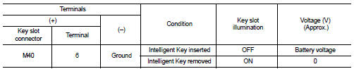
Is the inspection result normal? YES >> GO TO 6
NO >> GO TO 2
2.CHECK KEY SLOT POWER SUPPLY CIRCUIT
1. Turn ignition switch OFF.
2. Disconnect key slot connector.
3. Check voltage between slot connector and ground.
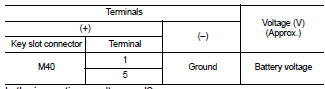
Is the inspection result normal? YES >> GO TO 3
NO >> Repair or replace key slot power supply circuit.
3.CHECK KEY SLOT GROUND CIRCUIT
Check continuity between key slot connector and ground.
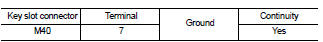
Is the inspection result normal? YES >> GO TO 4
NO >> Repair or replace key slot ground circuit.
4.CHECK KEY SLOT CIRCUIT
1. Turn ignition switch OFF.
2. Disconnect BCM and key slot connector.
3. Check continuity between BCM connector and key slot connector.
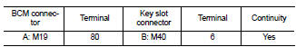
4. Check continuity between BCM connector and ground.
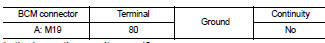
Is the inspection result normal? YES >> GO TO 5
NO >> Repair or replace harness between BCM and key slot.
5.CHECK KEY SLOT
Refer to DLK-83, "Component Inspection".
Is the inspection result normal? YES >> GO TO 6
NO >> Replace key slot. Refer to SEC-207, "Removal and Installation".
6.CHECK INTERMITTENT IN
Refer to GI-42, "Intermittent Incident".
>> Inspection End.
 Key slot
 Key cylinder switch