Nissan Altima (L32) 2007-2012 Service Manual: Timing chain
Removal and Installation
1. O-rings
2. Camshaft sprocket (INT)
3. Camshaft sprocket (EXH)
4. Chain tensioner
5. Spring
6. Chain tensioner plunger
7. Timing chain slack guide
8. Timing chain
9. Front cover
10. Chain guide
11. IVT solenoid valve
12. IVT cover
13. Crankshaft pulley bolt
14. Crankshaft pulley
15. Front oil seal
16. Balancer unit timing chain tensioner
17. Oil pump drive spacer
18. Crankshaft sprocket
19. Timing chain tension guide
20. Balancer unit timing chain
21. Balancer unit
22. Balancer unit sprocket
A. Follow the installation procedure
CAUTION: Apply new engine oil to parts as indicated in the illustration before installation.
REMOVAL
1. Support the engine and transaxle assembly with suitable tools.
2. Remove RH splash shield.
3. Remove the upper and lower oil pan, and oil strainer. Refer to EM-32, "Removal and Installation".
4. Remove generator. Refer to CHG-27, "Removal and Installation".
5. Remove engine cover.
6. Disconnect variable timing control solenoid harness connector.
7. Remove engine ground.
8. Remove the coolant overflow reservoir tank.
9. Position the RH engine compartment fuse and relay box aside.
10. Remove the RH engine mount and bracket. Refer to EM-72, "Removal and Installation".
11. Loosen bolts in the numerical order as shown.
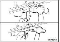
Remove the IVT (intake valve timing) control cover using Tool.
Tool number : KV10111100 (J-37228)
12. Pull chain guide between camshaft sprockets out through front cover.
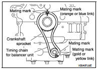
13. Set the No.1 cylinder at TDC on the compression stroke with the following procedure: a. Rotate the crankshaft pulley clockwise and align the mating marks to the timing indicator on the front cover.
b. At the same time, make sure that the mating marks on the camshaft sprockets are lined up as shown.
• If not lined up, rotate the crankshaft pulley one more turn to line up the mating marks to the positions as shown.
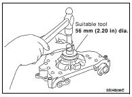
14. Remove crankshaft pulley with the following procedure: a. Hold the crankshaft pulley using suitable tool, then loosen the crankshaft pulley bolt, and pull the pulley out about 10 mm (0.39 in).
b. Attach suitable pulley puller in the M 6 (0.24 in diameter) thread hole on crankshaft pulley, and remove crankshaft pulley using a suitable puller.
15. Remove the front cover with the following procedure: a. Loosen the bolts in the numerical order as shown, and remove them.
b. Remove the front cover.
CAUTION: • Be careful not to damage the mounting surface.
16. Remove front oil seal using suitable tool, if necessary.
17. Remove timing chain with the following procedure: a. Push in the tensioner plunger. Insert a stopper pin into the hole on the tensioner body to secure the chain tensioner plunger and remove chain tensioner.
• Use a wire of 0.5 mm (0.02 in) diameter as a stopper pin.
b. Remove the timing chain.
c. Secure hexagonal part of the camshaft with a wrench and loosen the camshaft sprocket bolt and remove the camshaft sprocket for both camshafts.
CAUTION: • Do not rotate the crankshaft or camshafts while the timing chain is removed. It can cause damage to the valve and piston.
18. Remove the chain slack guide, tension guide, timing chain, and oil pump drive spacer.
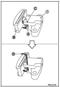
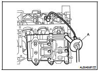
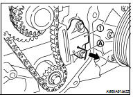
19. Press stopper tab (A) in the direction shown to push the timing chain slack guide (B) toward timing chain tensioner (for balancer unit) (1).
• The slack guide (B) is released by pressing the stopper tab (A). As a result, the slack guide (B) can be moved.
20. Insert stopper pin (D) into tensioner body hole (C) to secure timing chain slack guide (B).
NOTE: Use a hard metal pin with a diameter of approximately 1.2 mm (0.047 in) as a stopper pin.
21. Remove timing chain tensioner (for balancer unit) (1).
22. Secure width across flats of the balancer LH side shaft using a suitable tool. Loosen the balancer sprocket bolt.
23. Remove balancer unit timing chain, balancer unit sprocket and crankshaft sprocket.
24. Loosen bolts in order as shown, and remove balancer unit.
• Use Torx socket (size E14)
CAUTION: • Do not disassemble balancer unit.
INSPECTION AFTER REMOVAL
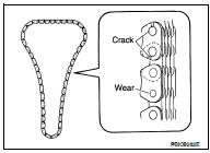
Timing Chain
Check the timing chain for cracks or excessive wear. If a defect is detected, replace it.
Balancer Unit Bolt Outer Diameter
• Measure outer diameters (d1, d2) at the two positions as shown.
• Measure d2 within the range A.
• If the value difference (d1 - d2) exceeds the limit, replace it with a new one.
Limit : 0.15 mm (0. 0059 in) or more
INSTALLATION
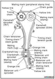
NOTE: • There may be two color variations of the link marks (link colors) on the timing chain.
• There are 26 links between the gold/yellow mating marks on the timing chain; and 64 links between the camshaft sprocket gold/yellow link and the crankshaft sprocket orange/blue link, on the timing chain side without the tensioner.
1. Make sure the crankshaft key points straight up.
2. Install the balancer unit and tighten the bolts in the numerical order as shown:
CAUTION: • When reusing a bolt, check its outer diameter before installation. Follow the Balancer Unit Bolt Outer Diameter procedure.
• Apply new engine oil to threads and seating surfaces of bolts.
• Check tightening angle with an angle wrench (A) or a protractor.
Do not make judgment by visual check alone.
3. Install the crankshaft sprocket and timing chain for the balancer unit.
• Make sure that the crankshaft sprocket is positioned with mating marks on the block and sprocket meeting at the top.
• Install it by lining up mating marks on each sprocket and timing chain.
4. Install timing chain tensioner (for balancer unit) (1).
• Fix the plunger at the most compressed position using a stopper pin (A), and then install it.
• Securely pull out ( ) the stopper pin after installing the timing chain tensioner (for balancer unit).
• Check matching mark position of balancer unit drive chain and each sprocket again.
5. Install timing chain and related parts.
• Install by lining up mating marks on each sprocket and timing chain as shown.
• Before and after installing timing chain tensioner, check again to make sure the mating marks have not slipped.
• After installing timing chain tensioner, remove the stopper pin, and make sure that the tensioner moves freely.
CAUTION: • For the following note, after the mating marks are aligned, keep them aligned by holding them by hand.
• To avoid skipped teeth, do not move crankshaft and camshaft until front cover is installed.
NOTE: Before installing chain tensioner, it is possible to change the position of mating mark on timing chain for that of each sprocket for alignment.
6. Install new front oil seal to front cover, using suitable tool • Install new oil seal in until it is flush with front end surface of front cover.
CAUTION: • Do not reuse oil seal.
• Be careful not to cause damage to circumference of oil seal.
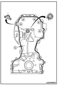
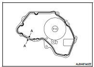
7. Install front cover with the following procedure: a. Install O-rings (B) to cylinder head and cylinder block.
b. Apply Genuine Silicone RTV Sealant or equivalent, to positions (A) specified as shown. Refer to GI-15, "Recommended Chemical Products and Sealants".
c. Make sure the mating marks on the timing chain and each sprocket are still aligned. Then install the front cover.
Sealant diameter (C) : 3.9 mm (0.154 in)
CAUTION: • Be careful not to damage the front oil seal during installation with the front end of the crankshaft.
d. Tighten front cover bolts in the numerical order as shown.
e. After all bolts are tightened, retighten them to the specified torque.
CAUTION: Wipe off any excess sealant leaking at the surface for installing the oil pan.
8. Install the chain guide between the camshaft sprockets.
9. Install IVT cover with the following procedure: a. Install IVT solenoid valve to IVT cover.
b. Install new O-ring to front cover.
c. Apply Silicone RTV Sealant to the IVT cover as shown.
• Apply Genuine Silicone RTV Sealant or equivalent, to positions specified as shown. Refer to GI-15, "Recommended Chemical Products and Sealants".
Diameter (A) : 3.0 - 4.0 mm (0.118 - 0.157 in)
d. Tighten the IVT cover bolts in the numerical order as shown.
10. Insert crankshaft pulley by aligning with crankshaft key.
• Tap its center with a plastic hammer to insert.
• Do not tap the belt hook.
11. Tighten crankshaft pulley bolts.
• Secure crankshaft pulley with tool to tighten the bolt.
• Perform angle tightening with the following procedure: a. Apply new engine oil to threads and seat surfaces of bolts.
b. Tighten to initial specifications:·
Crankshaft bolt : 42.1 N·m (4.3 kg-m, 31 ft-lb)
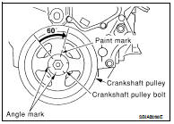
c. Apply a paint mark on the front cover, mating with any one of six easy to recognize stamp marks on bolt flange.
d. Turn crankshaft pulley bolt another 60° to 66° degrees [Target: 60° degrees].
• Check vertical mounting angle with movement of one stamp mark.
12. Installation of the remaining components is in the reverse order of removal.
 Camshaft
 Oil seal