Nissan Altima (L32) 2007-2012 Service Manual: Oil seal
Removal and Installation of Valve Oil Seal
REMOVAL
1. Turn crankshaft until the cylinder requiring new oil seals is at TDC. This will prevent valve from dropping into cylinder.
CAUTION: When rotating crankshaft, be careful to avoid scarring the front cover with the timing chain.
2. Remove camshaft relating to valve oil seal to be removed. Refer to EM-177, "Removal and Installation".
3. Remove valve lifters. Refer to EM-177, "Removal and Installation".
4. Remove valve collet, valve spring retainer and valve spring using Tool.
CAUTION: When working, take care not to damage valve lifter holes.
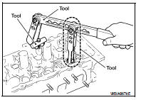
• Compress valve spring using Tool attachment, adapter.
Remove valve collet with magnet hand.
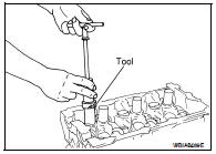
5. Remove valve oil seal using Tool.
Tool number : KV10107902 (J-38959)
INSTALLATION
1. Apply new engine oil to new valve oil seal joint surface and seal lip.
2. Press in valve oil seal to height (H) using Tool to specified height.
Tool number : — (J-39386)
NOTE: Dimension (H): height measured before valve spring seat installation.
Intake and exhaust : 14.3 - 14.9 mm (0.563 - 0.587 in)
3. Installation of the remaining components is in the reverse order of removal.
Removal and Installation of Front Oil Seal
REMOVAL
1. Remove the following parts: • Engine undercover.
• Drive belts. Refer to EM-121, "Removal and Installation".
• Radiator fan. Refer to CO-40, "Removal and Installation".
2. Remove the crankshaft pulley as follows: a. Remove the starter motor. Refer to STR-51, "Removal and Installation".
b. Lock the ring gear using Tool attached to the starter bolt hole.
Tool number : KV10117700 (J-44716)
CAUTION: Do not damage the ring gear teeth, or the signal plate teeth behind the ring gear when setting the stopper.
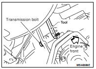
c. Loosen crankshaft pulley bolt using Tool and locate bolt seating surface at 10 mm (0.39 in) from its original position.
Tool number : KV10109300 ( — )
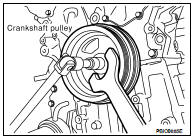
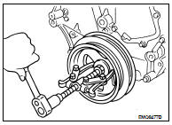
d. Position a pulley puller at recess hole of crankshaft pulley to remove crankshaft pulley.
CAUTION: Do not use a puller claw on crankshaft pulley periphery.
3. Remove front oil seal from front cover.
CAUTION: Be careful not to damage front cover or crankshaft.
INSTALLATION
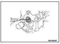
1. Apply new engine oil to new oil seal and install.
• Install new oil seal in the direction as shown.
CAUTION: Press fit straight and avoid causing burrs or tilting the oil seal.
• Press-fit oil seal until it becomes flush with the timing chain case end face, using suitable tool.
• Make sure the garter spring in the oil seal is in position and seal lip is not inverted.
2. Install crankshaft pulley and tighten the bolt in two steps.
• Lubricate thread and seat surface of the bolt with new engine oil.
• For the second step angle tighten using Tool.
Step 1 : 44 N·m (4.5 kg-m, 32 ft-lb)
Step 2 : 84° - 90° degrees clockwise
Tool number : KV10112100 (BT-8653-A)
3. Remove Tool attached to the starter bolt hole.
Tool number : KV10117700 (J-44716)
4. Installation of the remaining components is in reverse order of removal.
Removal and Installation of Rear Oil Seal
REMOVAL
1. Remove the engine and transaxle assembly. Refer to EM-202, "Removal and Installation".
2. Separate the transaxle from the engine. Refer to TM-26, "Removal and Installation" (M/T), TM-259, "Removal and Installation" (CVT).
3. Remove flywheel (M/T) or drive plate (CVT).
4. Remove rear oil seal retainer using Tool.
Tool Number : KV10111100 (J-37228)
CAUTION: • Be careful not to damage mating surface.
• If rear oil seal retainer is removed, replace it with a new one.
INSTALLATION
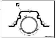
1. Remove old liquid gasket material from mating surface of cylinder block and oil pan using a suitable scraper.
2. Apply liquid gasket to the new rear oil seal retainer using suitable tool.
• Use Genuine Silicone RTV Sealant or equivalent. Refer to GI- 15, "Recommended Chemical Products and Sealants".
• Assembly should be completed within 5 minutes after coating.
3. Installation is in the reverse order of removal.
CAUTION: • When replacing an engine or transmission you must make sure the dowels are installed correctly during re-assembly.
• Improper alignment caused by missing dowels may cause vibration, oil leaks or breakage of drivetrain components.
 Camshaft
 Cylinder head