Nissan Altima (L32) 2007-2012 Service Manual: Camshaft
Removal and Installation
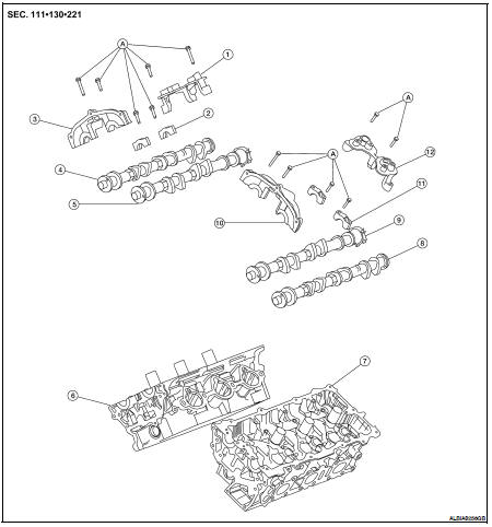
1. Camshaft position sensor bracket (RH)
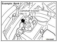
2. Camshaft brackets
3. No. 1 camshaft bracket (RH)
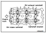
4. Camshaft (EXH) RH
5. Camshaft (INT) RH
6. Cylinder head (RH)
7. Cylinder head (LH)
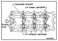
8. Camshaft (EXH) LH
9. Camshaft (INT) LH
10. No. 1 camshaft bracket (LH)
11. Camshaft brackets
12. Camshaft position sensor bracket (LH)
A. Follow installation procedure
CAUTION: Apply new engine oil to parts marked in illustration before installation.
REMOVAL
1. Remove the timing chains. Refer to EM-163, "Removal".
2. Remove the fuel rail and injectors. Refer to EM-146, "Removal and Installation".
3. Remove camshaft position brackets (RH shown LH similar).
4. Remove the intake and exhaust camshaft brackets and the camshafts.
• Mark the camshafts, camshaft brackets, and bolts so they are placed in the same position and direction for installation.
• Equally loosen the camshaft bracket bolts in several steps in the numerical order as shown.
5. Remove valve lifters.
NOTE: Identify installation positions to ensure proper installation.
6. Remove secondary timing chain tensioner from cylinder head • Remove secondary tensioner with its stopper pin attached.
NOTE: Stopper pin was attached when secondary timing chain was removed.
INSTALLATION
1. Before installation, remove any old Silicone RTV Sealant from component mating surfaces using a scraper.
• Remove the old Silicone RTV Sealant from the bolt holes and threads.
• Do not scratch or damage the mating surfaces.
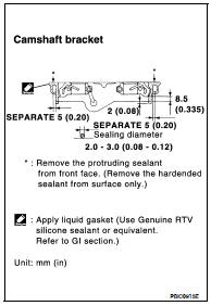
2. Before installing the front cam bracket, remove the old Silicone RTV Sealant from the mating surface using a scraper.
• Do not scratch or damage the mating surface.
3. Turn the crankshaft until No. 1 piston is set at TDC on the compression stroke.
• The crankshaft key should line up with the right bank cylinder center line as shown.
4. Install camshaft chain tensioners on both sides of cylinder head.
Refer to EM-155, "Removal and Installation".
5. Install valve lifters.
NOTE: Install them in original positions.
6. Install exhaust and intake camshafts and camshaft brackets.
• Intake camshaft has a drill mark on camshaft sprocket mounting flange.
• Follow your identification marks made during removal, or follow the identification marks that are present on the new camshafts components for proper placement and direction of the components.
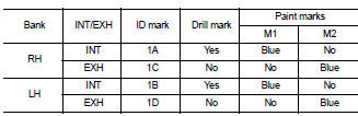
• Position the camshafts: RH exhaust camshaft dowel pin at about 10 o'clock.
LH exhaust camshaft dowel pin at about 2 o'clock.
7. Before installing camshaft brackets, apply sealant to mating surface of No. 1 camshaft bracket.
• Use Genuine Silicone RTV Sealant, or equivalent. Refer to GI-15, "Recommended Chemical Products and Sealants".
• Before installation, wipe off any protruding sealant.
• Refer to EM-111, "Precaution for Liquid Gasket".
• Install camshaft brackets in their original positions and direction.
Align the stamp marks as shown.
• If checking and adjusting any part of valve assembly or camshaft, check valve clearance according to the reference data. Refer to EM-124, "Valve Clearance".
• Tighten the camshaft brackets in the three steps, in numerical order as shown.
8. Measure difference in levels between front end faces of No. 1 camshaft bracket and cylinder head.
Standard : – 0.14 (– 0.0055 in)
• If measurement is outside the specified range, re-install camshaft and camshaft bracket.
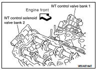
9. Install the IVT control solenoid valves with new gaskets. Refer to EM-155, "Removal and Installation".

10. If necessary, install camshaft position sensor (PHASE) (RH and LH bank.) 11. Install the fuel rail and injectors. Refer to EM-146, "Removal and Installation".
12. Install the timing chains. Refer to EM-166, "Installation".
Inspection after Installation
Camshaft Visual Check
Check camshaft for scratches, seizure and wear. Replace if necessary.
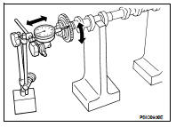
Camshaft Runout
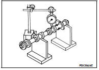
1. Put V-block on precise flat bed and support No. 2 and No. 4 journal of camshaft as shown.
2. Set dial gauges vertically to No. 3 journal as shown.
3. Turn camshaft in one direction slowly by hand, measure the camshaft runout on the dial gauges.
• Runout is the largest indicator reading after one full revolution.

4. If actual runout exceeds the limit, replace the camshaft.
Camshaft Cam Lobe Height
1. Measure camshaft cam lobe height as shown. Refer to EM-229, "Camshaft".
2. If wear has reduced the lobe height below specifications, replace the camshaft.
Camshaft Journal Clearance
Outer Diameter of Camshaft Journal
• Measure outer diameter of camshaft journal as shown.
Inner Diameter of Camshaft Bracket
1. Tighten camshaft bracket bolt with specified torque.
2. Using inside micrometer, measure inner diameter (A) of camshaft bearing.
Calculation of Camshaft Journal Clearance
(Journal clearance) = (inner diameter of camshaft bracket) – (outer diameter of camshaft journal)
When out of the specified range, replace either or both camshaft and cylinder head.
NOTICE: Inner diameter of camshaft bracket is manufactured together with cylinder head. Replace the whole cylinder head assembly.
Camshaft End Play
1. Install the camshaft in the cylinder head.
2. Install dial gauge in thrust direction on front end of camshaft.
Measure end play when camshaft is moved forward/backward (in direction to axis) as shown.

• If out of the specified range, replace with new camshaft and measure again.
• If out of the specified range again, replace with new cylinder head.
Camshaft Sprocket Runout
1. Put V-block on precise flat bed and support No. 2 and No. 4 journal of camshaft as shown.
2. Install camshaft sprocket on camshaft.
3. Measure camshaft sprocket runout.

4. If sprocket runout exceeds the limit, replace camshaft sprocket.
Valve Lifter
• Check if the surface of the valve lifter has any excessive wear or cracks, replace as necessary.
Valve Lifter Clearance
Outer Diameter of Valve Lifter
• Measure the outer diameter of the valve lifter. Refer to EM-229, "Camshaft".
• If out of the specified range, replace the valve lifter.
Valve Lifter Bore Diameter
• Using inside micrometer, measure diameter of valve lifter bore of cylinder head. Refer to EM-229, "Camshaft".
• If out of the specified range, replace the cylinder head assembly.
Calculation of Valve Lifter Clearance
• (Valve lifter clearance) = (hole diameter for valve lifter) – (outer diameter of valve lifter) Refer to EM-229, "Camshaft".
• If out of specified range, replace either or both valve lifter and cylinder head assembly.
Inspection after Installation
INSPECTION OF CAMSHAFT SPROCKET (INT) OIL GROOVE
WARNING: • Check when engine is cold so as to prevent burns from any splashing engine oil.
CAUTION: • Perform this inspection only when DTC P0011 is detected in self-diagnostic results of CONSULT III and it is directed according to inspection procedure of EC section. Refer to EC-1181, "Diagnosis Procedure".
1. Check engine oil level. Refer to LU-23, "Inspection".
2. Perform the following procedure so as to prevent the engine from being unintentionally started while checking.
a. Release fuel pressure. Refer to EC-1579, "Inspection".
b. Disconnect ignition coil and injector harness connectors if practical.
3. Remove IVT control solenoid valve.
4. Crank engine, and then make sure that engine oil comes out from IVT control cover oil hole. End cranking after checking.
WARNING: Be careful not to touch rotating parts (drive belts, idler pulley, and crankshaft pulley, etc.).
CAUTION: • Engine oil may squirt from IVT control solenoid valve installation hole during cranking. Use a shop cloth to prevent engine oil from splashing on worker, engine components and vehicle.
• Do not allow engine oil to get on rubber components such as drive belts or engine mount insulators.
Immediately wipe off any splashed engine oil.
5. Clean oil groove between oil strainer and IVT control solenoid valve if engine oil does not come out from IVT control cover oil hole.
6. Remove components between IVT control solenoid valve and camshaft sprocket (INT), and then check each oil groove for clogging.
• Clean oil groove if necessary.
7. After inspection, installation of the remaining components is in the reverse order of removal.
 Rear timing chain case
 Oil seal