Nissan Altima (L32) 2007-2012 Service Manual: On-vehicle repair
WHEEL HUB
Removal and Installation
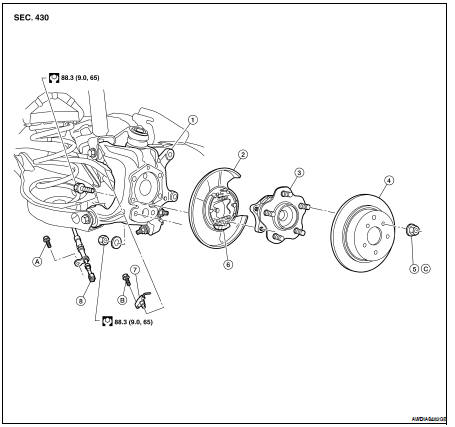
1. Knuckle
2. Baffle plate
3. Wheel hub assembly
4. Brake rotor
5. Wheel nut
6. Anchor block
7. ABS sensor
8. Parking brake cable
A. Refer to PB-6, "PEDAL TYPE : Exploded View" (Pedal type), PB-7, "LEVER TYPE : Exploded View" (Lever type).
B. Refer to BRC-63, "Removal and Installation" (ABS), BRC-134, "Removal and Installation" (TCS/ABS), BRC-236, "Removal and Installation" (VDC/TCS/ABS).
C. Refer to WT-66, "Adjustment".
REMOVAL
CAUTION: Wheel hub assembly does not require maintenance. If any of the following symptoms are noted, replace the wheel hub assembly.
• A growling noise is emitted from the wheel hub assembly while driving.
• The wheel hub assembly drags or turns roughly.
1. Remove the rear wheel and tire. Refer to WT-66, "Adjustment".
2. Remove the brake caliper assembly using power tool.
• The brake hose does not need to be disconnected from the brake caliper.
• Suspend the brake caliper assembly using wire, do not stretch the brake hose.
• Do not depress the brake pedal, or the caliper piston will pop out.
• Do not twist the brake hose.
3. Remove the brake rotor.
4. Remove the rear ABS sensor, then move it away from the wheel hub assembly.
CAUTION: Failure to remove the ABS sensor may result in damage to the sensor wires and the sensor being inoperative.
5. Remove the wheel hub assembly from knuckle.
INSPECTION AFTER REMOVAL
Check for any deformity, cracks, or damage on the wheel hub assembly, replace if necessary.
INSTALLATION
Installation is in the reverse order of removal.
• Check that the wheel bearings operate smoothly.
• Check that the wheel hub bearing axial end play is within specification.
Axial end play : 0.1 mm (0.004 in) or less
 On-vehicle maintenance
 Service data and specifications
(SDS)
Service data and specifications
(SDS)