Nissan Altima (L32) 2007-2012 Service Manual: P0605 ECM
Description
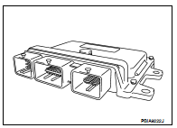
The ECM consists of a microcomputer and connectors for signal input and output and for power supply. The ECM controls the engine.
DTC Logic
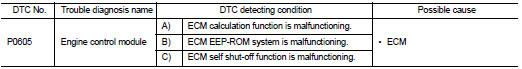
DTC DETECTION LOGIC
DTC CONFIRMATION PROCEDURE
1.PRECONDITIONING
If DTC Confirmation Procedure has been previously conducted, always turn ignition switch OFF and wait at least 10 seconds before conducting the next test.
>> GO TO 2.
2.PERFORM DTC CONFIRMATION PROCEDURE FOR MALFUNCTION A
1. Turn ignition switch ON.
2. Check 1st trip DTC.
Is 1st trip DTC detected? YES >> Go to EC-865, "Diagnosis Procedure".
NO >> GO TO 3.
3.PERFORM DTC CONFIRMATION PROCEDURE FOR MALFUNCTION B
1. wait at least 1 second.
2. Turn ignition switch OFF, wait at least 10 seconds, and then turn ON.
3. Check 1st trip DTC.
Is 1st trip DTC detected? YES >> Go to EC-865, "Diagnosis Procedure".
NO >> GO TO 4.
4.PERFORM DTC CONFIRMATION PROCEDURE FOR MALFUNCTION C
1. wait at least 1 second.
2. Turn ignition switch OFF, wait at least 10 seconds, and then turn ON.
3. Repeat step 2 for 32 times.
4. Check 1st trip DTC.
Is 1st trip DTC detected? YES >> Go to EC-865, "Diagnosis Procedure".
NO >> INSPECTION END
Diagnosis Procedure
1.INSPECTION START

1. Turn ignition switch ON.
2. Select “SELF-DIAG RESULTS” mode with CONSULT-III.
3. Touch “ERASE”.
4. Perform DTC CONFIRMATION PROCEDURE.
See EC-864, "DTC Logic".

1. Turn ignition switch ON.
2. Select Service $04 with GST.
3. Perform DTC CONFIRMATION PROCEDURE.
See EC-864, "DTC Logic".
Is the 1st trip DTC P0605 displayed again? YES >> GO TO 2.
NO >> INSPECTION END
2.REPLACE ECM
1. Replace ECM.
2. Go to EC-563, "ADDITIONAL SERVICE WHEN REPLACING CONTROL UNIT : Special Repair Requirement".
>> INSPECTION END
 P0603 ECM Power supply
 P0607 ECM