Nissan Altima (L32) 2007-2012 Service Manual: P0705 park/neutral position switch
Description
• The PNP switch assembly includes a transaxle range switch.
• The transaxle range switch detects the selector lever position and sends a signal to the TCM.
DTC Logic
DTC DETECTION LOGIC
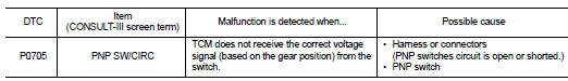
DTC CONFIRMATION PROCEDURE
CAUTION: Always drive vehicle at a safe speed.
NOTE: If “DTC CONFIRMATION PROCEDURE” has been previously performed, always turn ignition switch OFF.
Then wait at least 10 seconds before performing the next test.
1.CHECK DTC DETECTION

1. Turn ignition switch ON.
2. Select “DATA MONITOR”.
3. Start engine.
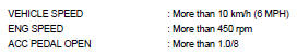
4. Drive vehicle and maintain the following conditions for at least 2 consecutive seconds.

Follow the procedure “With CONSULT-III”.
Is “P0705 PNP SW/CIRC” detected? YES >> Go to TM-307, "Diagnosis Procedure".
NO >> Check intermittent incident. Refer to GI-42, "Intermittent Incident".
Diagnosis Procedure
1.CHECK POWER SOURCE
1. Turn ignition switch OFF.
2. Disconnect PNP switch connector.
3. Turn ignition switch ON.
4. Check voltage between PNP switch harness connector F25 terminal 3 and ground.
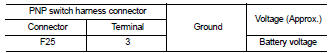
Is the inspection result normal? YES >> GO TO 2.
NO >> Check the following.
• Harness for short or open between ignition switch and PNP switch • 10A fuse (No. 4, located in fuse block)
• Ignition switch
2.CHECK HARNESS BETWEEN TCM AND PNP SWITCH (PART 1)
1. Turn ignition switch OFF.
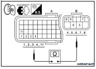
2. Disconnect TCM connector.
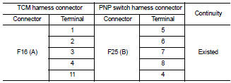
3. Check continuity between TCM harness connector F16 (A) terminal 1, 2, 3, 4, 11 and PNP switch harness connector F25 (B) terminal 5, 6, 7, 8, 4.
Is the inspection result normal? YES >> GO TO 3.
NO >> Repair or replace damaged parts.
3.CHECK HARNESS BETWEEN TCM AND PNP SWITCH (PART 2)
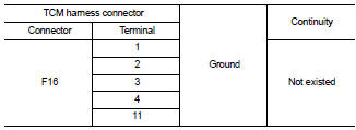
Check continuity between TCM harness connector F16 terminal 1, 2, 3, 4, 11 and ground.
Is the inspection result normal? YES >> GO TO 4.
NO >> Repair or replace damaged parts.
4.CHECK CVT POSITION
1. Remove control cable from manual lever. Refer to TM-433, "Exploded View".
2. Check continuity PNP switch connector terminals. Refer to TM-308, "Component Inspection (Park/Neutral Position Switch)" Is the inspection result normal? YES >> Adjust CVT position. Refer to TM-429, "Inspection and Adjustment".
NO >> GO TO 5.
5.DETECT MALFUNCTIONING ITEMS
Check TCM connector pin terminals for damage or loose connection with harness connector.
Is the inspection result normal? YES >> Replace TCM. Refer to TM-430, "Exploded View".
NO >> Repair or replace damaged parts.
Component Inspection (Park/Neutral Position Switch)
1.CHECK PNP SWITCH
1. Adjust PNP switch position. Refer to TM-429, "Inspection and Adjustment".
2. Check continuity between PNP switch terminals.
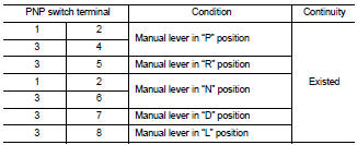
Is the inspection result normal? YES >> INSPECTION END
NO >> Replace PNP switch. Refer to TM-436, "Exploded View".
 P0703 stop lamp switch
 P0710 CVT fluid temperature sensor