Nissan Altima (L32) 2007-2012 Service Manual: P0703 stop lamp switch
Description
BCM detects ON/OFF state of the stop lamp switch and transmits the data to the TCM via CAN communication by converting the data to a signal.
DTC Logic
DTC DETECTION LOGIC
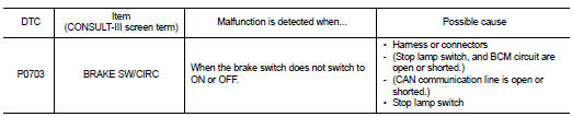
DTC CONFIRMATION PROCEDURE
CAUTION: Always drive vehicle at a safe speed. NOTE: If “DTC CONFIRMATION PROCEDURE” has been previously performed, always turn ignition switch OFF.
Then wait at least 10 seconds before performing the next test.
1.CHECK DTC DETECTION

1. Turn ignition switch ON.
2. Start engine.
3. Start vehicle for at least 3 consecutive seconds.
4. Perform “SELF-DIAG RESULTS” mode for “TRANSMISSION”.
Is “P0703 BRAKE SW/CIRC” detected? YES >> Go to TM-304, "Diagnosis Procedure".
NO >> Check intermittent incident. Refer to GI-42, "Intermittent Incident".
Diagnosis Procedure
1.CHECK STOP LAMP SWITCH CIRCUIT
1. Check and adjust the installation position of stop lamp switch. Refer to BR-13, "Inspection and Adjustment".
2. Turn ignition switch OFF.
3. Disconnect BCM connector M18.
4. Turn ignition switch ON.
5. Check voltage between BCM harness connector M18 terminal 26 and ground.
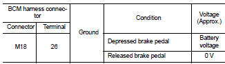
Is the inspection result normal? YES >> GO TO 5.
NO >> GO TO 2.
2.CHECK HARNESS BETWEEN STOP LAMP SWITCH AND BCM (PART 1)
1. Turn ignition switch OFF.
2. Disconnect stop lamp switch connector.
3. Check continuity between stop lamp switch harness connector E38 (A) terminal 2 and BCM harness connector M18 (B) terminal 26.
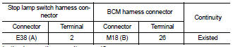
Is the inspection result normal? YES >> GO TO 3.
NO >> Repair or replace damaged parts.
3.CHECK HARNESS BETWEEN STOP LAMP SWITCH AND BCM (PART 2)
Check continuity between BCM harness connector M18 terminal 26 and ground.
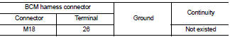
Is the inspection result normal? YES >> GO TO 4.
NO >> Repair or replace damaged parts.
4.CHECK STOP LAMP SWITCH
Check stop lamp switch. Refer to TM-305, "Component Inspection (Stop Lamp Switch)".
Is the inspection result normal? YES >> Check the following.
• Harness for short or open between battery and stop lamp switch
• 10A fuse (No. 7, located in fuse block)
NO >> Repair or replace stop lamp switch.
5.CHECK BCM

1. Turn ignition switch OFF.
2. Connect BCM connector M18.
3. Turn ignition switch ON.
4. Select “BRAKE SW 1” in “DATA MONITOR” of “BCM” and verify the proper operation of ON/OFF. Refer to BCS-47, "Reference Value".
Is the inspection result normal? YES >> GO TO 6.
NO >> Replace BCM. Refer to BCS-96, "Removal and Installation".
6.DETECT MALFUNCTIONING ITEMS
Check TCM connector pin terminals for damage or loose connection with harness connector.
Is the inspection result normal? YES >> Replace TCM. Refer to TM-430, "Exploded View".
NO >> Repair or replace damaged parts.
Component Inspection (Stop Lamp Switch)
1.CHECK STOP LAMP SWITCH
Check continuity between stop lamp switch terminals.
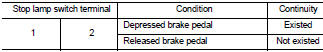
Is the inspection result normal? YES >> INSPECTION END
NO >> Replace stop lamp switch. BR-17, "Exploded View".
 U1010 control unit (CAN)
 P0705 park/neutral position switch