Nissan Altima (L32) 2007-2012 Service Manual: P0710 cvt fluid temperature sensor
Description
The CVT fluid temperature sensor detects the CVT fluid temperature and sends a signal to the TCM.
DTC Logic
DTC DETECTION LOGIC
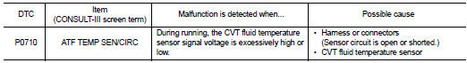
DTC CONFIRMATION PROCEDURE
CAUTION: Always drive vehicle at a safe speed.
NOTE: If “DTC CONFIRMATION PROCEDURE” has been previously performed, always turn ignition switch OFF.
Then wait at least 10 seconds before performing the next test.
1.CHECK DTC DETECTION (PART 1)

1. Turn ignition switch ON.
2. Select “DATA MONITOR”.
3. Check that output voltage of CVT fluid temperature sensor is within the range specified below.

Is the inspection result normal? YES >> Check intermittent incident. Refer to GI-42, "Intermittent Incident".
NO-1 (“ATF TEMP SEN” indicates 0.15 or less.)>>Refer to TM-132, "Diagnosis Procedure".
NO-2 (“ATF TEMP SEN” indicates 2.04 or more.)>>GO TO 2.
2.CHECK DTC DETECTION (PART 2)

1. Turn ignition switch ON.
2. Select “DATA MONITOR”.
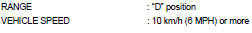
3. Start engine and maintain the following conditions for at least 14 minutes.

Follow the procedure “With CONSULT-III”.
Is “P0710 ATF TEMP SEN/CIRC” detected? YES >> Go to TM-132, "Diagnosis Procedure".
NO >> Check intermittent incident. Refer to GI-42, "Intermittent Incident".
Diagnosis Procedure
1.CHECK CVT FLUID TEMPERATURE SENSOR CIRCUIT
1. Turn ignition switch OFF.
2. Disconnect TCM harness connector.
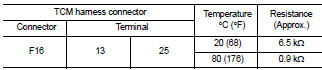
3. Check resistance between TCM harness connector F16 terminal 13 and 25.
Is the inspection result normal? YES >> GO TO 5.
NO >> GO TO 2.
2.CHECK HARNESS BETWEEN TCM AND CVT UNIT (CVT TEMPERATURE SENSOR) (PART 1)
1. Disconnect CVT unit harness connector.
2. Check continuity between TCM harness connector F16 (A) terminal 13, 25 and CVT unit harness connector F46 (B) terminal 17, 19.
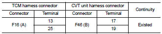
Is the inspection result normal? YES >> GO TO 3.
NO >> Repair or replace damaged parts.
3.CHECK HARNESS BETWEEN TCM AND CVT UNIT (CVT TEMPERATURE SENSOR) (PART 2)
Check continuity between TCM harness connector F16 terminal 13, 25 and ground.
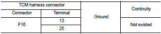
Is the inspection result normal? YES >> GO TO 4.
NO >> Repair or replace damaged parts.
4.CHECK CVT FLUID TEMPERATURE SENSOR
Check CVT fluid temperature sensor. Refer to TM-134, "Component Inspection (CVT Fluid Temperature Sensor)".
Is the inspection result normal? YES >> GO TO 5.
NO >> Replace transaxle assembly. Refer to TM-259, "Exploded View".
5.DETECT MALFUNCTIONING ITEMS
Check TCM connector pin terminals for damage or loose connection with harness connector.
Is the inspection result normal? YES >> Replace TCM. Refer to TM-254, "Exploded View".
NO >> Repair or replace damaged parts.
Component Inspection (CVT Fluid Temperature Sensor)
1.CHECK CVT FLUID TEMPERATURE SENSOR
Check resistance between CVT unit terminal 17 and 19.
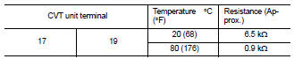
Is the inspection result normal? YES >> INSPECTION END
NO >> Replace transaxle assembly. Refer to TM-259, "Exploded View".
 P0705 park/neutral position switch
 P0715 input speed sensor (pri speed
sensor)
P0715 input speed sensor (pri speed
sensor)