Nissan Altima (L32) 2007-2012 Service Manual: P0740 torque converter clutch solenoid valve
Description
• The torque converter clutch solenoid valve is activated by the TCM in response to signals sent from the vehicle speed and accelerator pedal position sensors. Lock-up piston operation will then be controlled.
• Lock-up operation, however, is prohibited when CVT fluid temperature is too low.
• When the accelerator pedal is depressed (less than 2.0/8) in lock-up condition, the engine speed should not change abruptly. If there is a big jump in engine speed, there is no lock-up.
DTC Logic
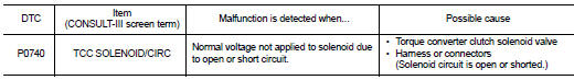
DTC DETECTION LOGIC
DTC CONFIRMATION PROCEDURE
NOTE: If “DTC CONFIRMATION PROCEDURE” has been previously performed, always turn ignition switch OFF.
Then wait at least 10 seconds before performing the next test.
1.CHECK DTC DETECTION

1. Turn ignition switch ON.
2. Wait at least 10 consecutive seconds.
3. Perform “SELF-DIAG RESULTS” mode for “TRANSMISSION”.

Follow the procedure “With CONSULT-III”.
Is “P0740 TCC SOLENOID/CIRC” detected? YES >> Go to TM-324, "Diagnosis Procedure".
NO >> Check intermittent incident. Refer to GI-42, "Intermittent Incident".
Diagnosis Procedure
1.CHECK TORQUE CONVERTER CLUTCH SOLENOID VALVE CIRCUIT
1. Turn ignition switch OFF.
2. Disconnect TCM harness connector.
3. Check resistance between TCM harness connector F16 terminal 38 and ground.
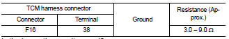
Is the inspection result normal? YES >> GO TO 5.
NO >> GO TO 2.
2.CHECK HARNESS BETWEEN TCM AND CVT UNIT (TORQUE CONVERTER CLUTCH SOLENOID VALVE) (PART 1)
1. Disconnect CVT unit harness connector.
2. Check continuity between TCM harness connector F16 (A) terminal 38 and CVT unit harness connector F46 (B) terminal 12.
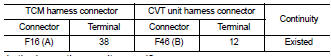
Is the inspection result normal? YES >> GO TO 3.
NO >> Repair or replace damaged parts.
3.CHECK HARNESS BETWEEN TCM AND CVT UNIT (TORQUE CONVERTER CLUTCH SOLENOID VALVE) (PART 2)
Check continuity between TCM harness connector F16 terminal 38 and ground.
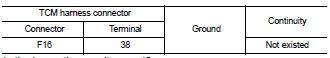
Is the inspection result normal? YES >> GO TO 4.
NO >> Repair or replace damaged parts.
4.CHECK TORQUE CONVERTER CLUTCH SOLENOID VALVE
Check torque converter clutch solenoid valve. Refer to TM-325, "Component Inspection (Torque Converter Clutch Solenoid Valve)".
Is the inspection result normal? YES >> GO TO 6.
NO >> GO TO 5.
5.CHECK DTC

1. Turn ignition switch ON.
2. Perform “SELF-DIAG RESULTS” mode for “TRANSMISSION”.
Is only “P0740 TCC SOLENOID/CIRC” detected? YES >> Replace control valve. Refer to TM-447, "Exploded View".
NO >> Replace transaxle assembly. Refer to TM-447, "Removal and Installation".
6.DETECT MALFUNCTIONING ITEMS
Check TCM connector pin terminals for damage or loose connection with harness connector.
Is the inspection result normal? YES >> Replace TCM. Refer to TM-430, "Exploded View".
NO >> Repair or replace damaged parts.
Component Inspection (Torque Converter Clutch Solenoid Valve)
1.CHECK TORQUE CONVERTER CLUTCH SOLENOID VALVE
Check resistance between CVT unit terminal 12 and ground.
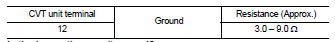
Is the inspection result normal? YES >> INSPECTION END
NO >> Replace control valve. Refer to TM-447, "Exploded View".
 P0730 belt damage
 P0744 A/T TCC S/V function (lock -up)