Nissan Altima (L32) 2007-2012 Service Manual: P0840 transmission fluid pressure sensor A (sec pressure sensor)
Description
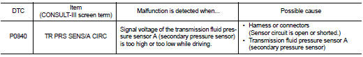
The transmission fluid pressure sensor A (secondary pressure sensor) detects secondary pressure of CVT and sends TCM the signal.
DTC Logic
DTC DETECTION LOGIC
DTC CONFIRMATION PROCEDURE
NOTE: If “DTC CONFIRMATION PROCEDURE” has been previously performed, always turn ignition switch OFF.
Then wait at least 10 seconds before performing the next test.
1.CHECK DTC DETECTION

1. Turn ignition switch ON.
2. Select “DATA MONITOR”.
3. Make sure that output voltage of CVT fluid temperature sensor is within the range below.
ATF TEMP SEN : 1.0 – 2.0 V
If out of range, drive the vehicle to decrease the voltage (warm up the fluid) or stop engine to increase the voltage (cool down the fluid)
4. Start engine and wait for at least 5 consecutive seconds.

Follow the procedure “With CONSULT-III”.
Is “P0840 TR PRS SENS/A CIRC” detected? YES >> Go to TM-160, "Diagnosis Procedure".
NO >> Check intermittent incident. Refer to GI-42, "Intermittent Incident".
Diagnosis Procedure
1.CHECK INPUT SIGNAL
1. Start engine.
2. Check voltage between TCM harness connector F16 terminal 15 and ground.
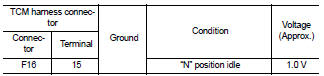
3. Turn ignition switch OFF.
Is the inspection result normal? YES >> GO TO 8.
NO >> GO TO 2.
2.CHECK POWER AND SENSOR GROUND
1. Turn ignition switch ON.
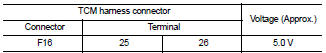
2. Check voltage between TCM harness connector F16 terminal 25 and 26.
Is the inspection result normal? YES >> GO TO 3.
NO >> GO TO 5.
3.CHECK HARNESS BETWEEN TCM AND CVT UNIT [TRANSMISSION FLUID PRESSURE SENSOR A (SECONDARY PRESSURE SENSOR)] (PART 1)
1. Turn ignition switch OFF.
2. Disconnect TCM harness connector and CVT unit harness connector.
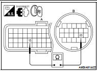
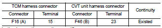
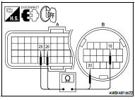
3. Check continuity between TCM harness connector F16 (A) terminal 15 and CVT unit harness connector F46 (B) terminal 23.
Is the inspection result normal? YES >> GO TO 4.
NO >> Repair or replace damaged parts.
4.CHECK HARNESS BETWEEN TCM AND CVT UNIT [TRANSMISSION FLUID PRESSURE SENSOR A (SECONDARY PRESSURE SENSOR)] (PART 2)
Check continuity between TCM harness connector F16 terminal 15 and ground.
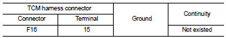
Is the inspection result normal? YES >> GO TO 7.
NO >> Repair or replace damaged parts.
5.CHECK HARNESS BETWEEN TCM AND CVT UNIT (SENSOR POWER AND SENSOR GROUND) (PART 1)
1. Turn ignition switch OFF.
2. Disconnect TCM harness connector and CVT unit harness connector.
3. Check continuity between TCM harness connector F16 (A) terminal 25, 26 and CVT unit harness connector F46 (B) terminal 19, 20.
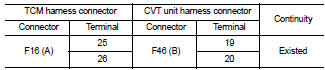
Is the inspection result normal?
YES >> GO TO 6.
NO >> Repair or replace damaged parts.
6.CHECK HARNESS BETWEEN TCM AND CVT UNIT (SENSOR POWER AND SENSOR GROUND) (PART 2)
Check continuity between TCM harness connector F16 terminal 25, 26 and ground.
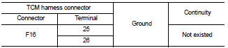
Is the inspection result normal? YES >> GO TO 7.
NO >> Repair or replace damaged parts.
7.CHECK TCM
1. Replace same type TCM. Refer to TM-254, "Exploded View".
2. Connect each connector.
3. Perform “DTC CONFIRMATION PROCEDURE”. Refer to TM-160, "DTC Logic".
Is “P0840 TR PRS SENS/A CIRC” detected? YES >> Replace transaxle assembly. Refer to TM-259, "Exploded View".
NO >> Replace TCM. Refer to TM-254, "Exploded View".
8.DETECT MALFUNCTIONING ITEMS
Check TCM connector pin terminals for damage or loose connection with harness connector.
Is the inspection result normal? YES >> Replace TCM. Refer to TM-254, "Exploded View".
NO >> Repair or replace damaged parts.
 P0826 manual mode switch
 P0841 pressure sensor function