Nissan Altima (L32) 2007-2012 Service Manual: P0826 manual mode switch
Description
Manual mode switch is installed in CVT control device. The manual mode switch sends shift up and shift down switch signals to TCM.
TCM sends the switch signals to combination meter via CAN communication line. Then manual mode switch position is indicated on the CVT position indicator.
DTC Logic
DTC DETECTION LOGIC
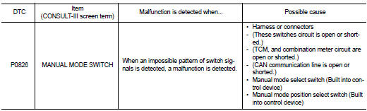
DTC CONFIRMATION PROCEDURE
CAUTION: Always drive vehicle at a safe speed.
NOTE: If “DTC CONFIRMATION PROCEDURE” has been previously performed, always turn ignition switch OFF.
Then wait at least 10 seconds before performing the next test.
1.CHECK DTC DETECTION

1. Turn ignition switch ON.
2. Select “DATA MONITOR”.
3. Drive vehicle and maintain the following conditions for at least 2 consecutive seconds.
MMODE : On
Is “P0826 MANUAL MODE SWITCH” detected? YES >> Go to TM-157, "Diagnosis Procedure".
NO >> Check intermittent incident. Refer to GI-42, "Intermittent Incident".
Diagnosis Procedure
1.CHECK MANUAL MODE SWITCH SIGNALS

1. Turn ignition switch ON.
2. Select “DATA MONITOR”.
3. Check the ON/OFF operations of each monitor item.
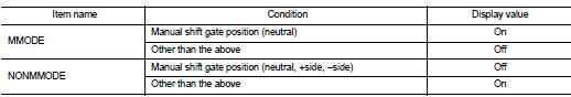
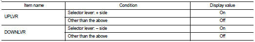

Drive vehicle in the manual mode, and confirm that the actual gear position and the meter's indication of the position mutually coincide when the selector lever is shifted to the “+ (up)” or “− (down)” side (1st ⇔ 6th gear).
Is the inspection result normal? YES >> GO TO 7.
NO >> GO TO 2.
2.CHECK HARNESS BETWEEN CVT DEVICE AND COMBINATION METER (PART 1)
1. Turn ignition switch OFF.
2. Disconnect CVT device harness connector and combination meter harness connector.
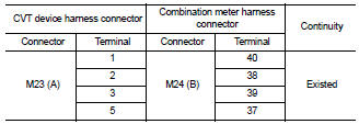
3. Check continuity between CVT device harness connector M23 (A) terminal 1, 2, 3 and 5 and combination meter harness connector M24 (B) terminal 40, 38, 39 and 37.
Is the inspection result normal? YES >> GO TO 3.
NO >> Repair or replace damaged parts.
3.CHECK HARNESS BETWEEN CVT DEVICE AND COMBINATION METER (PART 2)
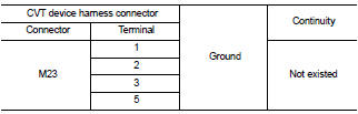
Check continuity between CVT device harness connector M23 terminal 1, 2, 3, and 5 and ground.
Is the inspection result normal? YES >> GO TO 4.
NO >> Repair or replace damaged parts.
4.CHECK GROUND CIRCUIT (PART 1)
Check continuity between CVT device harness connector M23 terminal 4 and ground.
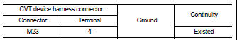
Is the inspection result normal? YES >> GO TO 5.
NO >> Repair or replace damaged parts.
5.CHECK GROUND CIRCUIT (PART 2)
1. Turn ignition switch ON.
2. Check voltage between CVT device harness connector M23 terminal 4 and ground.
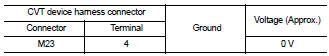
Is the inspection result normal? YES >> GO TO 6.
NO >> Repair or replace damaged parts.
6.CHECK MANUAL MODE SWITCH
Check manual mode switch. Refer to TM-159, "Component Inspection (Manual Mode Switch)".
Is the inspection result normal? YES >> GO TO 7.
NO >> Repair or replace damaged parts.
7.DETECT MALFUNCTIONING ITEMS
Check TCM connector pin terminals for damage or loose connection with harness connector.
Is the inspection result normal? YES >> Replace TCM. Refer to TM-254, "Exploded View".
NO >> Repair or replace damaged parts.
Component Inspection (Manual Mode Switch)
1.CHECK MANUAL MODE SWITCH
Check continuity between CVT device terminals.
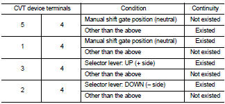
Is the inspection result normal? YES >> INSPECTION END
NO >> Repair or replace damaged parts.
 P0778 pressure control solenoid B
electrical (sec pressure solenoid
valve)
P0778 pressure control solenoid B
electrical (sec pressure solenoid
valve) P0840 transmission fluid pressure
sensor A (sec pressure sensor)
P0840 transmission fluid pressure
sensor A (sec pressure sensor)