Nissan Altima (L32) 2007-2012 Service Manual: P0841 pressure sensor function
Description
Using the engine load (throttle position), the primary pulley revolution speed, and the secondary pulley revolution speed as input signal, TCM changes the operating pressure of the primary pulley and the secondary pulley and changes the groove width of the pulley to control the gear ratio.
DTC Logic
DTC DETECTION LOGIC
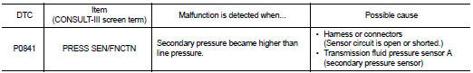
DTC CONFIRMATION PROCEDURE
CAUTION: Always drive vehicle at a safe speed. NOTE: If “DTC CONFIRMATION PROCEDURE” has been previously performed, always turn ignition switch OFF.
Then wait at least 10 seconds before performing the next test.
1.CHECK DTC DETECTION

1. Turn ignition switch ON.
2. Select “DATA MONITOR”.
3. Start engine and maintain the following conditions for at least 12 consecutive seconds.

Is “P0841 PRESS SEN/FNCTN” detected? YES >> Go to TM-344, "Diagnosis Procedure".
NO >> Check intermittent incident. Refer to GI-42, "Intermittent Incident".
Diagnosis Procedure
1.CHECK LINE PRESSURE
Perform line pressure test. Refer to TM-423, "Inspection and Judgment".
Is the inspection result normal? YES >> GO TO 2.
NO >> Repair or replace damaged parts. Refer to TM-423, "Inspection and Judgment".
2.CHECK TRANSMISSION FLUID PRESSURE SENSOR A (SECONDARY PRESSURE SENSOR) SYSTEM
Check transmission fluid pressure sensor A (secondary pressure sensor) system. Refer to TM-341, "Description".
Is the inspection result normal? YES >> GO TO 3.
NO >> Repair or replace damaged parts.
3.CHECK PRESSURE CONTROL SOLENOID VALVE A (LINE PRESSURE SOLENOID VALVE)
1. Turn ignition switch OFF.
2. Disconnect CVT unit connector.
3. Check pressure control solenoid valve A (line pressure solenoid valve). Refer to TM-345, "Component Inspection [Pressure Control Solenoid Valve A (Line Pressure Solenoid Valve)]".
Is the inspection result normal? YES >> GO TO 4.
NO >> Replace transaxle assembly. Refer to TM-447, "Exploded View".
4.CHECK PRESSURE CONTROL SOLENOID VALVE B (SECONDARY PRESSURE SOLENOID VALVE)
Check pressure control solenoid valve B (secondary pressure solenoid valve). Refer to TM-345, "Component Inspection [Pressure Control Solenoid Valve B (Secondary Pressure Solenoid Valve)]".
Is the inspection result normal? YES >> GO TO 5.
NO >> Replace transaxle assembly. Refer to TM-447, "Exploded View".
5.CHECK STEP MOTOR SYSTEM
Check step motor system. Refer to TM-361, "Description".
Is the inspection result normal? YES >> GO TO 6.
NO >> Repair or replace damaged parts.
6.DETECT MALFUNCTIONING ITEMS
Check TCM connector pin terminals for damage or loose connection with harness connector.
Is the inspection result normal? YES >> Replace TCM. Refer to TM-430, "Exploded View".
NO >> Repair or replace damaged parts.
Component Inspection [Pressure Control Solenoid Valve A (Line Pressure Solenoid Valve)]
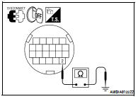
1.CHECK PRESSURE CONTROL SOLENOID VALVE A (LINE PRESSURE SOLENOID VALVE)
Check resistance between CVT unit terminal 2 and ground.
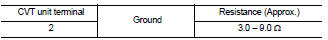
Is the inspection result normal? YES >> INSPECTION END
NO >> Replace transaxle assembly. Refer to TM-447, "Exploded View".
Component Inspection [Pressure Control Solenoid Valve B (Secondary Pressure Solenoid Valve)]
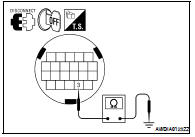
1.CHECK PRESSURE CONTROL SOLENOID VALVE B (SECONDARY PRESSURE SOLENOID VALVE)
Check resistance between CVT unit terminal 3 and ground.
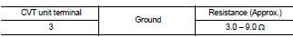
Is the inspection result normal? YES >> INSPECTION END
NO >> Replace transaxle assembly. Refer to TM-447, "Exploded View".
 P0840 transmission fluid pressure sensor A (sec pressure sensor)
 P0868 secondary pressure down