Nissan Altima (L32) 2007-2012 Service Manual: P0868 secondary pressure down
Description
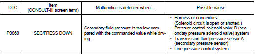
The pressure control solenoid valve B (secondary pressure solenoid valve) regulates the secondary pressure to suit the driving condition in response to a signal sent from the TCM.
DTC Logic
DTC DETECTION LOGIC
DTC CONFIRMATION PROCEDURE
CAUTION: Always drive vehicle at a safe speed.
NOTE: If “DTC CONFIRMATION PROCEDURE” has been previously performed, always turn ignition switch OFF.
Then wait at least 10 seconds before performing the next test.
1.CHECK DTC DETECTION
1. Turn ignition switch ON.
2. Select “DATA MONITOR”.
3. Make sure that output voltage of CVT fluid temperature sensor is within the range below.
ATF TEMP SEN : 1.0 – 2.0 V
If out of range, drive the vehicle to decrease the voltage (warm up the fluid) or stop engine to increase the voltage (cool down the fluid)
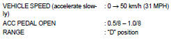
4. Start engine and maintain the following conditions for at least 10 consecutive seconds.
Is “P0868 SEC/PRESS DOWN” detected? YES >> Go to TM-346, "Diagnosis Procedure".
NO >> Check intermittent incident. Refer to GI-42, "Intermittent Incident".
Diagnosis Procedure
1.CHECK LINE PRESSURE
Perform line pressure test. Refer to TM-423, "Inspection and Judgment".
Is the inspection result normal? YES >> GO TO 2.
NO >> Repair or replace damaged parts. Refer to TM-423, "Inspection and Judgment".
2.CHECK PRESSURE CONTROL SOLENOID VALVE B (SECONDARY PRESSURE SOLENOID VALVE)
1. Turn ignition switch OFF.
2. Disconnect CVT unit connector.
3. Check pressure control solenoid valve B (secondary pressure solenoid valve). Refer to TM-347, "Component Inspection [Pressure Control Solenoid Valve B (Secondary Pressure Solenoid Valve)]".
Is the inspection result normal? YES >> GO TO 3.
NO >> Replace transaxle assembly. Refer to TM-447, "Exploded View".
3.CHECK PRESSURE CONTROL SOLENOID VALVE A (LINE PRESSURE SOLENOID VALVE)
Check pressure control solenoid valve A (line pressure solenoid valve). Refer to TM-347, "Component Inspection [Pressure Control Solenoid Valve A (Line Pressure Solenoid Valve)]".
Is the inspection result normal? YES >> GO TO 4.
NO >> Replace transaxle assembly. Refer to TM-447, "Exploded View".
4.CHECK TRANSMISSION FLUID PRESSURE SENSOR A (SECONDARY PRESSURE SENSOR) SYSTEM
Check transmission fluid pressure sensor A (secondary pressure sensor) system. Refer to TM-341, "DTC Logic".
Is the inspection result normal? YES >> GO TO 5.
NO >> Repair or replace damaged parts.
5.DETECT MALFUNCTIONING ITEMS
Check TCM connector pin terminals for damage or loose connection with harness connector.
Is the inspection result normal? YES >> Replace TCM. Refer to TM-430, "Exploded View".
NO >> Repair or replace damaged parts.
Component Inspection [Pressure Control Solenoid Valve A (Line Pressure Solenoid Valve)]
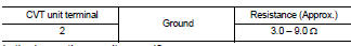
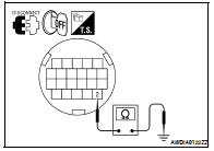
1.CHECK PRESSURE CONTROL SOLENOID VALVE A (LINE PRESSURE SOLENOID VALVE)
Check resistance between CVT unit terminal 2 and ground.
Is the inspection result normal? YES >> INSPECTION END
NO >> Replace transaxle assembly. Refer to TM-447, "Exploded View".
Component Inspection [Pressure Control Solenoid Valve B (Secondary Pressure Solenoid Valve)]
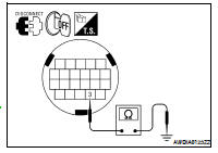
1.CHECK PRESSURE CONTROL SOLENOID VALVE B (SECONDARY PRESSURE SOLENOID VALVE)
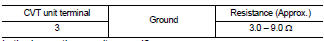
Check resistance between CVT unit terminal 3 and ground.
Is the inspection result normal? YES >> INSPECTION END
NO >> Replace transaxle assembly. Refer to TM-447, "Exploded View".
 P0841 pressure sensor function
 P1701 transmission control module (power supply)