Nissan Altima (L32) 2007-2012 Service Manual: P0850 PNP Switch
Description
When the shift lever position is P or N (CVT), Neutral position (M/T), park/neutral position (PNP) switch is ON.
ECM detects the position because the continuity of the line (the ON signal) exists.
DTC Logic
DTC DETECTION LOGIC
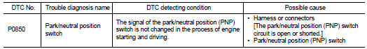
DTC CONFIRMATION PROCEDURE
1.INSPECTION START
Do you have CONSULT-III? Do you have CONSULT-III? YES >> GO TO 2.
NO >> GO TO 5.
2.PRECONDITIONING
If DTC Confirmation Procedure has been previously conducted, always turn ignition switch OFF and wait at least 10 seconds before conducting the next test.
>> GO TO 3.
3.CHECK PNP SWITCH FUNCTION

1. Turn ignition switch ON.
2. Select “P/N POSI SW” in “DATA MONITOR” mode with CONSULT-III. Then check the “P/N POSI SW” signal under the following conditions.
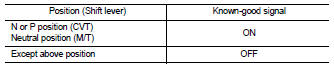
Is the inspection result normal? YES >> GO TO 4.
NO >> Go to EC-871, "Diagnosis Procedure".
4.PERFORM DTC CONFIRMATION PROCEDURE
1. Select “DATA MONITOR” mode with CONSULT-III.
2. Start engine and warm it up to normal operating temperature.
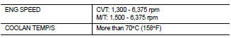
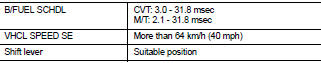
3. Maintain the following conditions for at least 50 consecutive seconds.
CAUTION: Always drive vehicle at a safe speed.
4. Check 1st trip DTC.
Is 1st trip DTC detected? YES >> Go to EC-871, "Diagnosis Procedure".
NO >> INSPECTION END
5.PERFORM COMPONENT FUNCTION CHECK
Perform component function check. Refer to EC-871, "Component Function Check".
NOTE: Use component function check the overall function of the park/neutral position (PNP) switch circuit. During this check, a 1st trip DTC might not be confirmed.
Is the inspection result normal? YES >> INSPECTION END NO >> Go to EC-871, "Diagnosis Procedure".
Component Function Check
1.PERFORM COMPONENT FUNCTION CHECK
1. Turn ignition switch ON.
2. Check the voltage between ECM harness connector and ground.
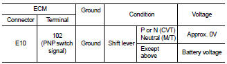
Is the inspection result normal? YES >> INSPECTION END
NO >> Go to EC-871, "Diagnosis Procedure".
Diagnosis Procedure
1.CHECK PNP SWITCH POWER SUPPLY CIRCUIT
1. Turn ignition switch OFF.
2. Disconnect Park/neutral position (PNP) switch harness connector.
3. Turn ignition switch ON.
4. Check the voltage between PNP switch harness connector and ground.
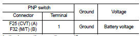
Is the inspection result normal? YES >> GO TO 2.
NO >> Repair open circuit or short to ground or short to power in harness or connectors.
2.CHECK PNP SWITCH INPUT SIGNAL CIRCUIT FOR OPEN AND SHORT-I
1. Turn ignition switch OFF.
2. Disconnect ECM harness connector.
3. Check the continuity between PNP switch harness connector and ECM harness connector.
4. Also check harness for short to ground and short to power.
Is the inspection result normal? YES >> GO TO 4.
NO-1 >> Repair open circuit or short to ground or short to power in harness or connectors.
NO-2 >> CVT: GO TO 3.
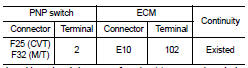
3.CHECK PNP SWITCH INPUT SIGNAL CIRCUIT FOR OPEN AND SHORT-II
1. Check the continuity between PNP switch harness connector and ECM harness connector.
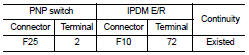
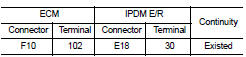
2. Check the continuity between IPDM E/R harness connector and ECM harness connector.
3. Also check harness for short to ground and short to power.
Is the inspection result normal? YES >> GO TO 4.
NO >> Repair open circuit or short to ground or short to power in harness or connectors.
4.CHECK PNP SWITCH
Refer to TM-308, "Component Inspection (Park/Neutral Position Switch)" (CVT) or TM-20, "Inspection" (M/T).
Is the inspection result normal? YES >> GO TO 5.
NO >> Replace PNP switch.
5.CHECK INTERMITTENT INCIDENT
Refer to GI-42, "Intermittent Incident".
>> INSPECTION END
 P0643 sensor power supply
 P1148 closed loop control