Nissan Altima (L32) 2007-2012 Service Manual: P1778 step motor - function
Description
• The step motor's 4 aspects of ON/OFF change according to the signal from TCM. As a result, the flow of line pressure to primary pulley is changed and pulley ratio is controlled.
• This diagnosis item is detected when electrical system is OK, but mechanical system is NG.
• This diagnosis item is detected when the state of the changing the speed mechanism in unit does not operate normally.
DTC Logic
DTC DETECTION LOGIC
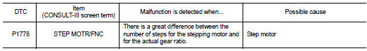
DTC CONFIRMATION PROCEDURE
CAUTION: • Always drive vehicle at a safe speed.
• Before starting “DTC CONFIRMATION PROCEDURE”, confirm “Hi” or “Mid” or “Low” fixation by “PRI SPEED” and “VEHICLE SPEED” on “DATA MONITOR MODE”.
• If hi-geared fixation occurred, go to TM-187, "Diagnosis Procedure". NOTE: If “DTC CONFIRMATION PROCEDURE” has been previously performed, always turn ignition switch OFF.
Then wait at least 10 seconds before performing the next test.
1.CHECK DTC DETECTION

1. Turn ignition switch ON.
2. Select “DATA MONITOR”.
3. Make sure that output voltage of CVT fluid temperature sensor is within the range below.
ATF TEMP SEN : 1.0 – 2.0 V
If out of range, drive the vehicle to decrease the voltage (warm up the fluid) or stop engine to increase the voltage (cool down the fluid)
4. Start engine and maintain the following conditions for at least 30 consecutive seconds.
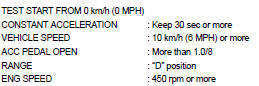

Follow the procedure “With CONSULT-III”.
Is “P1778 STEP MOTR/FNC” detected? YES >> Go to TM-187, "Diagnosis Procedure".
NO >> Check intermittent incident. Refer to GI-42, "Intermittent Incident".
Diagnosis Procedure
1.CHECK STEP MOTOR SYSTEM
Check step motor system. Refer to TM-184, "Description".
Is the inspection result normal?
YES >> GO TO 2.
NO >> Repair or replace damaged parts.
2.CHECK INPUT SPEED SENSOR (PRIMARY SPEED SENSOR) SYSTEM
Check input speed sensor (primary speed sensor) system. Refer to TM-135, "Description".
Is the inspection result normal? YES >> GO TO 3.
NO >> Repair or replace damaged parts.
3.CHECK OUTPUT SPEED SENSOR (SECONDARY SPEED SENSOR) SYSTEM
Check output speed sensor (secondary speed sensor) system. Refer to TM-138, "Description".
Is the inspection result normal? YES >> GO TO 4.
NO >> Repair or replace damaged parts.
4.DETECT MALFUNCTIONING ITEMS
Check TCM connector pin terminals for damage or loose connection with harness connector.
Is the inspection result normal? YES >> Replace TCM. Refer to TM-254, "Exploded View".
NO >> Repair or replace damaged parts.
 P1777 step motor
 Shift lock system