Nissan Altima (L32) 2007-2012 Service Manual: Steering gear and linkage
Exploded View
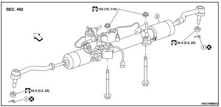
1. Cotter pin
2. Steering gear assembly

Removal and Installation
REMOVAL
1. Remove the front tires.
2. Remove undercover using power tool.
3. Remove lower side bolt of lower joint.
4. Remove cotter pin (1), and then loosen the nut.
5. Remove steering outer socket (2) from steering knuckle (3) so as not to damage ball joint boot (4) using the Tool.
CAUTION: Temporarily tighten the nut to prevent damage to threads and to prevent the Tool from suddenly coming off.
Tool number : HT72520000 (J-25730-A)
6. Remove high and low pressure piping of hydraulic piping, and then drain power steering fluid. Refer to ST-8, "Draining".
7. Remove steering hydraulic piping bracket from front suspension member.
8. Remove SSPS valve harness connector. Refer to ST-28, "Exploded View".
9. Remove bolts and nuts of steering gear assembly, and then remove steering gear assembly from vehicle.
INSPECTION AFTER REMOVAL
Check for fluid leaks or damage to steering gear. If any exist, replace steering gear as an assembly.
INSTALLATION
Installation is in the reverse order of removal. For tightening specifications, refer to ST-17, "Exploded View".
• When installing lower joint to steering gear assembly, follow the procedure listed below.
- Set rack of steering gear in the neutral position.
NOTE: To get the neutral position of rack, turn gear-sub assembly and measure the distance of inner socket, and then measure the intermediate position of the distance.
- Align rear cover cap projection (A) with the marking position (B) of gear housing assembly.
- Install slit part of lower joint (C) aligning with the projection (A) of rear cover cap (1). Make sure that the slit part of lower joint (C) is aligned with both the projection (A) of rear cover cap (1) and the marking position (B) of gear housing assembly.
• After installation, bleed air from the steering hydraulic system.
Refer to ST-8, "Inspection".
• Perform final tightening of nuts and bolts on each part under unladen conditions with tires on level ground when removing steering gear assembly. Check wheel alignment. Refer to FSU-7, "Inspection and Adjustment".
INSPECTION AFTER INSTALLATION
Make sure that steering wheel operates smoothly by turning several times from full left stop to full right stop.
 Steering wheel
 Power steering oil pump