Nissan Altima (L32) 2007-2012 Service Manual: Radiator
Removal and Installation
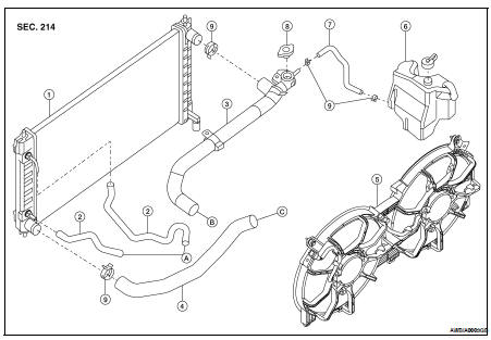
1. Radiator
2. CVT oil cooler hose (if equipped)
3. Radiator hose (upper)
4. Radiator hose (lower)
5. Cooling fan
6. Reservoir tank
7. Reservoir hose
8. Radiator filler cap
9. Clamps
A. To CVT (if equipped)
B. To water outlet
C. To water inlet
WARNING: Never remove the radiator cap when the engine is hot. Serious burns could occur from high pressure coolant escaping from the radiator. Wrap a thick cloth around the cap. Slowly turn it a quarter turn to allow built-up pressure to escape. Carefully remove the cap by turning it all the way.
REMOVAL 1. Drain engine coolant from the radiator. Refer to CO-12, "Changing Engine Coolant".
2. Remove front grille (Sedan only). Refer to EXT-38, "Removal and Installation".
3. Remove front bumper fascia (Coupe only). Refer to EXT-13, "Removal and Installation".
4. Remove engine undercover.
5. Remove front air duct. Refer to EM-129, "Removal and Installation".
6. Remove A/C condenser. Refer to HA-42, "Removal and Installation for Condenser".
7. Disconnect radiator upper and lower hoses.
8. Disconnect the CVT oil cooler hoses, if equipped. Plug the hoses to prevent CVT oil loss.
9. Remove radiator.
CAUTION: • Do not damage or scratch the radiator core when removing.
INSTALLATION
Installation is in the reverse order of removal.
INSPECTION
Radiator
1. Check radiator for mud or clogging. If necessary, clean radiator as follows: • Be careful not to bend or damage the radiator fins.
• When radiator is cleaned without removal, remove all surrounding parts such as cooling fan, radiator shroud and horns. Then tape the harness and electrical connectors to prevent water from entering.
a. Apply water by hose to the back side of the radiator core, point the hose vertically downward.
b. Apply water again to all radiator core surfaces once per minute.
c. Stop washing when no more dirt flows off the radiator.
d. Blow air into the back side of radiator core, point the air hose vertically downward.
• Use compressed air lower than 490 kPa (5 kg/cm2, 71 psi) and keep distance more than 30 cm (11.8 in).
e. Blow air again into all the radiator core surfaces once per minute until no water sprays out.
2. Inspect radiator for leaks as follows: a. Apply pressure using Tool.

WARNING: To prevent the risk of the hose coming undone while under pressure, securely fasten it down with a hose clamp.
Attach a hose to the oil cooler as well (CVT model only).
b. Check for leakage.
 On-vehicle repair
 Cooling fan