Nissan Altima (L32) 2007-2012 Service Manual: Cooling fan
Removal and Installation
1. Fan blade
2. Fan shroud and motor assembly
REMOVAL
1. Drain engine coolant from the radiator. Refer to CO-35, "Changing Engine
Coolant".
CAUTION:
Perform when engine is cold.
2. Remove CVT control module (if equipped). Refer to TM-430, "Removal and
Installation".
3. Remove battery tray. Refer to PG-139, "Removal and Installation".
4. Disconnect radiator upper hose.
5. Disconnect fan motor connectors.
6. Remove radiator cooling fan assembly.
INSTALLATION
Installation is in the reverse order of removal.
• After installation refill engine coolant and check for leaks. Refer to CO-35,
"Changing Engine Coolant" and
CO-34, "System Inspection".
CAUTION:
Do not spill coolant in engine compartment. Use a shop cloth to absorb coolant.
• Cooling fans are controlled by ECM. For details, refer to EC-1099, "System
Description".
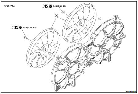
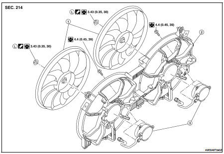
Disassembly and Assembly of Cooling Fan
1. Fan blade
2. Fan shroud
3. Fan motor
DISASSEMBLY
1. Remove fan blade nut.
2. Remove fan blade from fan motor.
3. Remove fan motor bolts and remove fan motor from fan shroud.
ASSEMBLY
Assembly is in the reverse order of disassembly.
Removal and Installation
1. Radiator
2. CVT oil cooler hose (if equipped)
3. Radiator hose (upper)
4. Radiator hose (lower)
5. Cooling fan
6. Reservoir tank
7. Reservoir hose
8. Radiator fil ...
Removal and Installation
1. Water pump
2. O-rings
WARNING:
Never remove the radiator cap when the engine is hot. Serious burns could occur
from high pressure
coolant escaping from the radiato ...
Other materials: Rear-facing child restraint installation
using the seat belts
WARNING
The three-point seat belt with Automatic
Locking Retractor (ALR) must be
used when installing a child restraint.
Failure to use the ALR mode will result
in the child restraint not being properly
secured. The restraint could tip over or
be loose and cause injury to a child in a
sudden stop o ...
Resetting the drive computer
The drive computer is divided across three
screens:
Speed
Trip Distance & Time
Fuel Economy
1. Press the or
buttons until the
desired drive computer screen is
displayed.
2. Press the OK button to bring up the drive
computer Reset menu.
3. Use the or
to select the desired
option. Then press ...
Settings
The setting mode allows you to change the
information displayed in the vehicle information
display. It also allows you to change
vehicle functions:
VDC
Driver Assistance
Clock
Meter Settings
Vehicle Settings
Maintenance
Alarm
Tire Pressures
Unit
Language
Factory Reset
VDC
The VDC Settin ...
 Radiator
 Water pump