Nissan Altima (L32) 2007-2012 Service Manual: Rear door glass
Exploded View
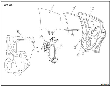
1. Rear door
2. Door glass run
3. Door glass
4. Inside seal
5. Partition sash
6. Rear window seal
7. Door rear, glass
8. Regulator assembly
9. Window motor
10. Water shield
Removal and Installation
REMOVAL
1. Remove the rear door finisher. Refer to INT-34, "Removal and Installation".
2. Remove the plastic vapor barrier, being careful not to tear/damage it.
3. Temporarily reconnect the power window switch to the door harness.
4. Operate the power window switch to raise/lower the door glass until the door glass bolts (A) can be seen.
5. Remove the door glass bolts (A).
6. Remove the door glass.
7. Remove the partition sash from the glass run.
• Remove the partition sash bolt (lower) (B) and screw (upper) (A) to remove the sash.
8. Remove the partition glass from the inside of the door in the direction as shown.
INSTALLATION
Installation is in the reverse order of removal.
• After installation inspect and adjust as necessary.
Inspection and Adjustment
FITTING INSPECTION
• Make sure the glass is securely fit into the glass run groove.
• Lower the glass slightly [approx. 10 to 20 mm (0.39 to 0.79 in)], and make sure the clearance to the sash is parallel. If the clearance between the glass and sash is not parallel, loosen the regulator mounting bolts, guide rail mounting bolts, and glass and carrier plate mounting bolts to correct the glass position.
 Front regulator
 Rear regulator