Nissan Altima (L32) 2007-2012 Service Manual: Front regulator
Exploded View
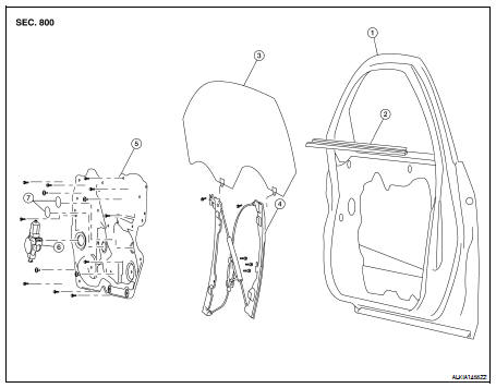
1. Door
2. Inside seal
3. Door glass
4. Regulator assembly
5. Door module assembly
6. Window motor
7. Cover
Removal and Installation
REMOVAL
1. Remove the front door finisher. For Sedan Refer to INT-34, "Removal and Installation". For Coupe Refer to INT-12, "Removal and Installation" 2. Remove the bolt hole covers.
3. Remove the upper door module assembly bolts and the upper window regulator bolts.
4. Reconnect the power window switch to raise/lower the door glass until the door glass bolts (A) can be seen.
5. Remove the door glass bolts.
6. Raise the door glass and hold with a suction lifter (A).

7. Disconnect the window motor connector (A).
8. Remove the door module assembly.
INSPECTION AFTER REMOVAL
Check the regulator assembly for the following items. If a malfunction is detected, replace or grease it.
• Excessive cable wear.
• Regulator channel deformation (A).
• Apply grease for each sliding part. Apply grease at the application points (A) as shown.
INSTALLATION
Installation is in the reverse order of removal.
Inspection and Installation
Inspection after Removal
Check the regulator assembly for the following items. If a malfunction is detected, replace or grease it.
• Wire wear
• Regulator deformation
• Grease condition for each sliding part
Apply at the locations shown multi-purpose grease.
Setting of Limit Switch
If any of the following work has been done, set the limit switch (integrated in the motor).
• Removal and installation of the regulator.
• Removal and installation of the motor from the regulator.
• Removal and installation of the door glass.
• Removal and installation of the glass run.
SYSTEM INITIALIZATION
If any of the following work has been done, initialize the system.
• Electric power supply to power window switch or motor is interrupted by blown fuse or disconnecting battery cable, etc.
• Removal and installation of the regulator assembly.
• Removal and installation of the motor from the regulator assembly.
• Removal and installation of the harness connector of the power window switch.
• Operate the regulator assembly as a unit.
• Removal and installation of the door glass.
• Removal and installation of the door glass run.
Initialization
After installing each component to the vehicle, follow the steps below.
1. Disconnect the negative battery terminal or disconnect power window switch harness connector temporarily, then reconnect after at least 1 minute.
2. Turn ignition switch ON.
3. Open the window fully by operating the power window switch. (Exclude this procedure if the window is already fully opened) 4. Fully raise the power window switch in up direction (auto close position) and hold, keep holding the switch even when window is completely closed and then release after 4 second has passed.
5. Inspect of the anti-pinch system function.
NOTE: Initialization may be cancelled with continuous opening and closing operation.In this case, initialize the system.
INSPECT THE FUNCTION OF THE ANTI-PINCH SYSTEM.
1. Fully open the door glass.
2. Place a wooden piece (wooden hammer handle etc.) at near fully closed position.
3. Carry out fully closing operation with auto up switch.
CAUTION: • Do not inspect with pinching a part of worker's body, a hand etc. Work carefully not to be pinched.
• Check that auto up function is normal before inspection following the system initialization. • Check that the glass reverses without pinching the wooden piece, is lowered approx.150 mm (5.91 in) or for 2 seconds and then stops.
• The glass should not be raised with power window main switch operated while it is reversing or lowering.
FITTING INSPECTION
• Make sure the glass is securely set into the glass run groove.
• Lower the glass slightly [approx. 10 to 20 mm (0.39 to 0.79 in)] and make sure the clearance to the sash is parallel. If the clearance between the glass and sash is not parallel, loosen the regulator mounting bolts, guide rail mounting bolts, and glass and guide rail mounting bolts to adjust the glass position.
 Front door glass
 Rear door glass