Nissan Altima (L32) 2007-2012 Service Manual: Rear view camera
Diagnosis Procedure
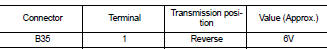
1.CHECK POWER SUPPLY CIRCUIT (REAR VIEW CAMERA SIDE)
Check voltage between rear view camera harness connector and ground.
Is inspection result normal? YES >> GO TO 4
NO >> GO TO 2
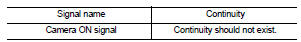
2.CHECK POWER SUPPLY CIRCUIT (CONTINUITY)
1. Turn ignition switch OFF.
2. Disconnect rear view camera and rear view camera control unit connectors.
3. Check continuity between rear view camera harness connector B35 (A) terminal 1 and rear view camera control unit harness connector B31 (B) terminal 8.

4. Check continuity between rear view camera harness connector B35 (A) terminal 1 and ground.
Is inspection result normal? YES >> GO TO 3
Is inspection result normal? YES >> GO TO 3
3.CHECK POWER SUPPLY CIRCUIT (CAMERA CONTROL UNIT SIDE)
1. Connect rear view camera control unit harness connector.
2. Turn ignition switch ON.
3. Check voltage between rear view camera control unit harness connector and ground.
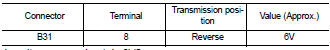
Is voltage approximately 6V? YES >> Inspection End.
NO >> Replace rear view camera control unit. Refer to AV-458, "Removal and Installation - Sedan".
4.CHECK GROUND CIRCUIT
1. Turn ignition switch OFF.
2. Disconnect rear view camera harness connector.
3. Check continuity between rear view camera harness connector B35 terminal 2 and ground.
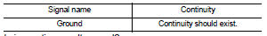
Is inspection result normal? YES >> Inspection End.
NO >> Repair harness or connector.
 Rear view camera control unit
 Bose speaker AMP