Nissan Altima (L32) 2007-2012 Service Manual: Refrigeration system
HFC-134a (R-134a) Service Procedure
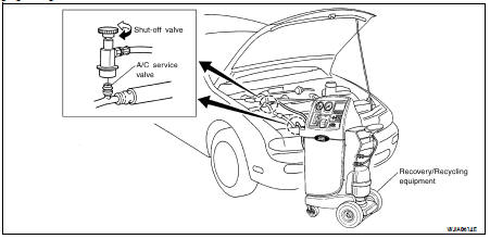
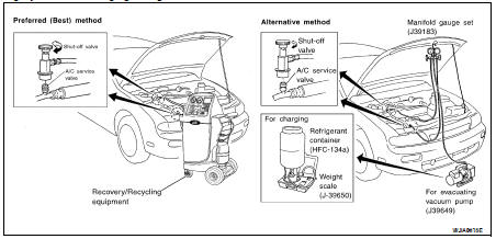
SETTING OF SERVICE TOOLS AND EQUIPMENT
WARNING: Avoid breathing the A/C refrigerant and oil vapor or mist. Exposure may irritate eyes, nose, and throat.
Remove the HFC-134a (R-134a) from the A/C system using certified service equipment meeting the requirements of SAE J2210 (R-134a recycling equipment) or SAE J2201 (R-134a recovery equipment).
If an accidental system discharge occurs, ventilate the work area before resuming service. Additional health and safety information may be obtained from the refrigerant and oil manufacturers.
Discharging Refrigerant
Evacuating System and Charging Refrigerant
Discharging, Evacuating, and Recharging the A/C System
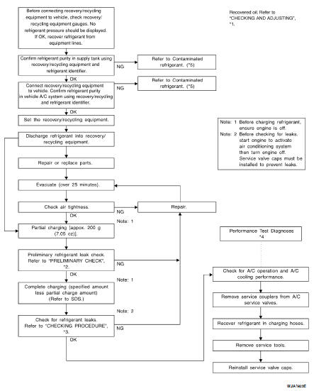
*1 HA-21, "Maintenance of Oil Quantity in Compressor"
*2 HA-25, "Checking of Refrigerant Leaks"
*3 HA-25, "Checking of Refrigerant Leaks"
*4 HAC-5, "Operational Check"
*5 HA-4, "Contaminated Refrigerant"
Checking of Refrigerant Leaks
Perform a visual inspection of all refrigeration parts, fittings, hoses and components for signs of A/C oil leakage, damage and corrosion. A/C oil leakage may indicate an area of refrigerant leakage. Allow extra inspection time in these areas when using either an electronic refrigerant leak detector or fluorescent dye leak detector.
If dye is observed, confirm the leak with an electronic refrigerant leak detector. It is possible a prior leak was repaired and not properly cleaned.
When searching for leaks, do not stop when one leak is found but continue to check for additional leaks at all system components and connections.
When searching for refrigerant leaks using an electronic leak detector, move the probe along the suspected leak area at 25 - 50 mm (1 - 2 in) per second and no further than 6 mm (1/4 in) from the component.
CAUTION: Moving the electronic leak detector probe slower and closer to the suspected leak area will improve the chances of finding a leak.
 Oil
Oil Fluorescent leak detector