Nissan Altima (L32) 2007-2012 Service Manual: U0140 Can comm circuit
Description
CAN (Controller Area Network) is a serial communication line for real time
application. It is an on-vehicle multiplex
communication line with high data communication speed and excellent error
detection ability. Many electronic
control units are equipped onto a vehicle, and each control unit shares
information and links with other
control units during operation (not independent). In CAN communication, control
units are connected with 2
communication lines (CAN H line, CAN L line) allowing a high rate of information
transmission with less wiring.
Each control unit transmits/receives data but selectively reads required data
only.
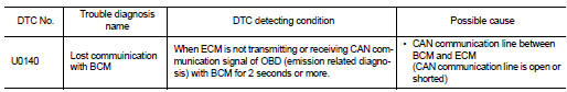
DTC Logic
DTC DETECTION LOGIC
DTC CONFIRMATION PROCEDURE
1.PERFORM DTC CONFIRMATION PROCEDURE
1. Turn ignition switch ON and wait at least 3 seconds.
2. Check DTC.
Is DTC detected?
YES >> EC-678, "Diagnosis Procedure".
Description
CAN (Controller Area Network) is a serial communication line for real time
application. It is an on-vehicle multiplex
communication line with high data communication speed and excellen ...
Description
CAN (Controller Area Network) is a serial communication line for real time
application. It is an on-vehicle multiplex
communication line with high data communication speed and excelle ...
 U0101 Can comm circuit
 U1001 Can comm circuit