Nissan Altima (L33) 2013-2018 Owners Manual: Warning systems switch (if so equipped)
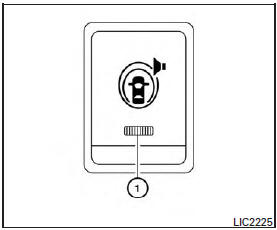
The warning systems switch is used to temporarily
turn off the warning systems (Lane Departure
Warning (LDW) and Blind SpotWarning (BSW)
systems) that are activated using the settings
menu in the vehicle information display.
When the warning systems switch is turned off,
the indicator 1 on the switch is off. The indicator
will also be off if all of the warning systems are
deactivated using the settings menu.
The BSW system will turn on the Blind Spot
indicator lights, located inside the vehicle next to
the outside mirrors, if a vehicle is located in the
detection zone. If the turn signal is activated in the
direction of the detected vehicle, a chime sounds
twice and the BSW indicator light will flash. For
additional information, see “Blind Spot Warning
(BSW) System / Lane DepartureWarning (LDW)
System” in the “Starting and driving” section.
The LDW system will sound a warning chime and
the LDW indicator light (orange) in the vehicle
information display blinks to alert the driver if the
vehicle is traveling close to either the left or the
right of a traveling lane when detected by the
camera unit. For additional information, see
“Blind Spot Warning (BSW) System / Lane Departure
Warning (LDW) System” in the “Starting
and driving” section.
The heated steering wheel system is designed to
operate only when the surface temperature of the
steering wheel is below approximately 68°F
(20°C).
Push the heated steering wheel switch to w ...
The vehicle should be driven with the Vehicle
Dynamic Control (VDC) system on for most driving
conditions.
If the vehicle is stuck in mud or snow, the VDC
system reduces the engine output to r ...
 Heated steering wheel (if so equipped)
 Vehicle Dynamic Control (VDC) off switch