Nissan Altima (L32) 2007-2012 Service Manual: Rear timing chain case
Component
1. Timing chain tensioner
2. Internal chain guide
3. Timing chain tensioner
4. Camshaft sprocket (EXH)
5. Timing chain (secondary)
6. Timing chain (primary)
7. Camshaft sprocket (INT)
8. Camshaft sprocket (INT)
9. Timing chain (secondary)
10. Camshaft sprocket (EXH)
11. Slack guide
12. Crankshaft sprocket
13. Rear timing chain case
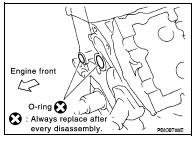
14. Tension guide
15. O-ring
• Refer to EM-111, "Precaution for Liquid Gasket".
• Before installation, wipe off any protruding sealant.
CAUTION: • After removing timing chain, do not turn the crankshaft and camshaft separately, or the valves will strike the pistons.
• When installing camshafts, chain tensioners, oil seals, or other sliding parts, lubricate contacting surfaces with new engine oil.
• Apply new engine oil to bolt threads and seat surfaces when installing camshaft sprockets, camshaft brackets, and crankshaft pulley.
• Before disconnecting fuel hose, release fuel pressure. Refer to EC-1579, "Inspection".
• Before removing the upper oil pan, remove the crankshaft position sensor (POS).
• Be careful not to damage sensor edges.
• Do not spill engine oil or coolant on drive belts.
Removal and Installation
REMOVAL
1. Remove the engine assembly. Refer to EM-202, "Removal and Installation".
2. Remove the primary and secondary timing chains. Refer to EM-163, "Removal".
3. Remove the rear timing chain case.
CAUTION: • Do not remove the plate metal cover for the oil passage.
• After removing the chain case, do not apply any load to the case that might bend it.
a. Loosen and remove the rear timing chain case bolts in the order as shown.
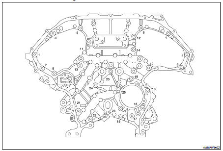
b. Cut the sealant with an appropriate tool and remove the rear timing chain case.
4. Remove O-rings to timing chain case and cylinder block.
5. Use a scraper to remove all of the old Silicone RTV Sealant from the front and rear timing chain case and opposite mating surfaces.
CAUTION: Do not damage the mating surfaces.

6. Remove all old Silicone RTV Sealant from all the bolt holes and bolts.
CAUTION: Do not damage the threads or mating surfaces.
INSTALLATION
1. Install O-rings on cylinder block.
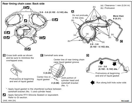
2. Apply Genuine Silicone RTV Sealant or equivalent, to the rear timing chain case using Tool as shown.
Refer to GI-15, "Recommended Chemical Products and Sealants".
Tool number : WS39930000 ( — )
CAUTION: • For (a), completely wipe out liquid gasket extended on a portion touching at engine coolant.
• Apply liquid gasket on installation position of water pump and cylinder completely.
3. Align the rear timing chain case and water pump assembly with the dowel pins (RH and LH) on the cylinder block and install the case. Make sure the O-rings stay in place during installation.
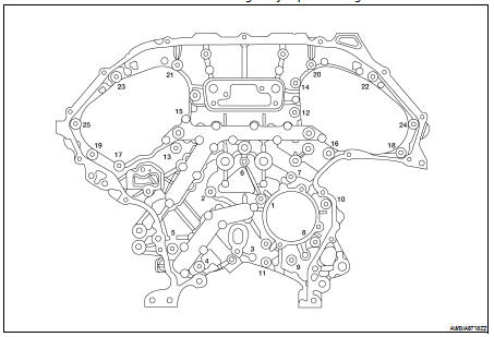
a. Tighten the bolts in the numerical order as shown. There are two bolt lengths used. Follow the chart below for proper bolt length specifications.
b. After all bolts are initially tightened, retighten them to the specification in the numerical order as shown.
4. Install the primary and secondary timing chains. Refer to EM-166, "Installation".
5. Install the engine assembly. Refer to EM-202, "Removal and Installation".
 Timing chain
 Camshaft