Nissan Altima (L32) 2007-2012 Service Manual: Water pump
Removal and Installation
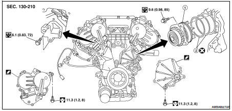
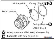
1. Water pump
2. O-rings
WARNING: Never remove the radiator cap when the engine is hot. Serious burns could occur from high pressure coolant escaping from the radiator.
CAUTION: • When removing water pump assembly, be careful not to get coolant on drive belt.
• Water pump cannot be disassembled and should be replaced as a unit.
• After installing water pump, connect hose and clamp securely, then check for leaks using radiator cap tester.
REMOVAL
1. Drain engine coolant from the radiator. Refer to CO-35, "Changing Engine Coolant".
CAUTION: Perform when the engine is cold.
2. Remove engine coolant reservoir tank. Refer to CO-38, "Removal and Installation".
3. Remove RH wheel and tire. Refer to WT-66, "Adjustment".
4. Remove the fender protector (RH). Refer to EXT-19, "Removal and Installation" (Coupe models) or EXT- 40, "Removal and Installation" (Sedan models).
5. Remove drive belts.
6. Remove the drive belt auto tensioner and the idler pulley. Refer to EM-122, "Removal and Installation of Drive Belt Auto-tensioner".
7. Support engine and remove the front engine insulator and bracket. Refer to EM-202, "Removal and Installation".
8. Remove water drain plug on water pump side of cylinder block.
9. Remove IVT control valve cover and water pump cover.
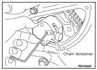
10. Remove the timing chain tensioner assembly.
a. Pull the lever down to release the plunger stopper tab.
b. Insert the stopper pin into the tensioner body hole to hold the lever and keep the plunger stopper tab released.
NOTE: An allen wrench [(1.2 mm (0.047 in)] is used for a stopper pin as an example.
c. Insert the plunger stopper tab into the tensioner body by pressing the slack guide.
d. Keep the slack guide pressed and hold the plunger stopper tab in by pushing the stopper pin deeper through the lever and into the chain tensioner body hole.
e. Make a gap between water pump gear and timing chain, by turning the crankshaft pulley approximately 20° clockwise.
11. Remove chain tensioner.
CAUTION: Be careful not to drop bolts inside chain case.
12. Remove the three water pump bolts. Make a gap between water pump gear and timing chain, by turning crankshaft pulley counterclockwise until timing chain loosens on water pump sprocket.
13. Screw M8 bolts [pitch: 1.25 mm (0.49 in) length: approx. 50 mm (1.97 in)] into water pumps upper and lower bolt holes until they reach the timing chain case. Then, alternately tighten each bolt for a half turn, and pull out the water pump.
CAUTION: • Pull straight out while preventing vane from contacting socket in installation area.
• Remove water pump without causing sprocket to contact timing chain.
14. Remove M8 bolts and O-rings from water pump.
INSPECTION AFTER REMOVAL
• Visually check that there is no significant dirt or rusting on the water pump body and vane.
• Check that there is no looseness in the vane shaft, and that it turns smoothly when rotated by hand.
• If the water pump does not perform properly, replace the water pump assembly.
INSTALLATION
1. Install new O-rings to water pump.
2. Apply engine oil and coolant to the O-rings as shown.
• Locate the O-ring with white paint mark to engine front side.
3. Install the water pump.
CAUTION: Do not allow cylinder block to interfere with the O-rings when installing the water pump.
• Check that timing chain and water pump sprocket are engaged.
• Insert water pump by tightening bolts alternately and evenly.
4. Remove dust and foreign material completely from backside of chain tensioner and from installation area of rear timing chain case.
5. Turn the crankshaft pulley approximately 20° clockwise so that the timing chain on the timing chain tensioner side is loose.
NOTE: When installing the timing chain tensioner, engine oil should be applied to the oil hole and tensioner.
6. Install the timing chain tensioner.
7. Remove the stopper pin.
8. Install IVT control valve cover and water pump cover.
a. Before installing, remove all traces of sealant from mating surface of water pump cover and IVT control valve cover using a scraper.
Also remove traces of sealant from the mating surface of the front cover.
b. Apply a continuous bead of RTV Silicone Sealant or equivalent, to mating surface of IVT control valve cover and water pump cover. Refer to GI-15, "Recommended Chemical Products and Sealants".
9. Install water drain plug on water pump side of cylinder block. Refer to CO-35, "Changing Engine Coolant".
10. Install idler pulley. Refer to EM-122, "Removal and Installation of Drive Belt Auto-tensioner".
11. Installation of remaining components is in the reverse order of removal.
• After installation refill engine coolant and check for leaks. Refer to CO-35, "Changing Engine Coolant" and CO-34, "System Inspection".
CAUTION: Do not spill coolant in engine compartment. Use a shop cloth to absorb coolant.
• After starting engine, let idle for three minutes, then rev engine up to 3,000 rpm under no load to purge air from the high-pressure chamber of the chain tensioner. The engine may produce a rattling noise.
This indicates that air still remains in the chamber and is not a matter of concern.
 Cooling fan
 Thermostat and thermostat housing