Nissan Altima (L32) 2007-2012 Service Manual: Drive belts
Checking Drive Belts
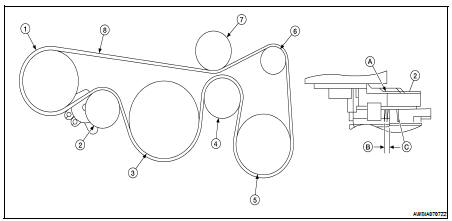
1. Power steering pump
2. Drive belt auto-tensioner
3. Crankshaft
4. Idler pulley
5. A/C compressor pulley
6. Generator pulley
7. Idler pulley
8. Drive belt
A. Indicator
B. Possible use range (for new belt)
C. Belt replacement
WARNING: Inspect and check the drive belts with the engine off.
1. Inspect belt for cracks, fraying, wear or oil adhesion. If necessary, replace with a new one.
2. Rotate the crankshaft pulley two times then check the belt tension.
NOTE: • Inspect drive belt tension when engine is cold.
Tension Adjustment
• Belt tension is not manually adjustable, it is automatically adjusted by the drive belt auto-tensioner.
Removal and Installation
REMOVAL
1. Remove the front RH side cover.
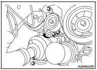
2. While securely holding the hexagonal part in pulley center of drive belt auto-tensioner, move in the direction of arrow (loosening direction of tensioner) using suitable tool.
WARNING: • Avoid placing hand in a location where pinching may occur if the holding tool accidentally comes off.
CAUTION: • Do not loosen the auto-tensioner pulley bolt. (Do not turn it counterclockwise.) If turned counterclockwise, the complete auto-tensioner must be replaced as a unit, including pulley.
3. Insert a rod approximately 6 mm (0.24 in) in diameter through the rear of tensioner into retaining boss to lock tensioner pulley.
• Leave tensioner pulley arm locked until belt is installed again.
4. Loosen auxiliary drive belt from water pump pulley and then remove it from the other pulleys.
INSTALLATION
1. Install the drive belt onto all of the pulleys.
CAUTION: Confirm belts are completely set on the pulleys.
2. Release tensioner, and apply tension to belt.
WARNING: • Avoid placing hand in a location where pinching may occur if the holding tool accidentally comes off.
CAUTION: • Do not loosen the auto-tensioner pulley bolt. (Don't turn it counterclockwise. If turned counterclockwise, the complete auto-tensioner must be replaced as a unit, including pulley.
3. Turn crankshaft pulley clockwise several times to equalize tension between each pulley.
4. Confirm tension of belt at indicator is within the allowable use range. Refer to EM-16, "Checking Drive Belts".
Removal and Installation of Drive Belt Auto-tensioner
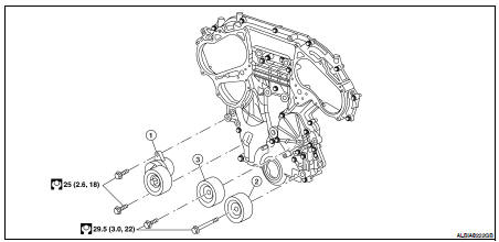
1. Drive belt auto-tensioner
2. Idler pulley
3. A/C idler pulley
REMOVAL
CAUTION: The complete auto-tensioner must be replaced as a unit, including the pulley.
1. Remove the front RH engine cover.
2. Remove the drive belt EM-121, "Removal and Installation".
• Insert a rod approximately 6 mm (0.24 in) in diameter through the rear of tensioner into the retaining boss to lock tensioner pulley.
3. Remove the drive belt auto-tensioner, with power tool.
CAUTION: Do not loosen the auto-tensioner pulley bolt. (Don't turn it counterclockwise. If turned counterclockwise, the complete auto-tensioner must be replaced as a unit, including pulley.
NSTALLATION
Installation is in the reverse order of removal.
CAUTION: • If there is damage greater than peeled paint, replace drive belt auto-tensioner units.
• Do not swap the pulley between the new and old auto-tensioner units.
 Spark plug
 Air cleaner filter