Nissan Altima (L32) 2007-2012 Service Manual: Intake manifold collector
Removal and Installation
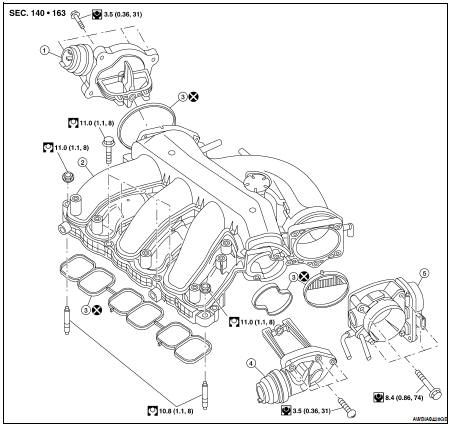
1. Power valve (RH)
2. Intake manifold collector
3. Gasket
4. Power valve (LH)
5. Electric throttle control actuator
REMOVAL
WARNING: • To avoid the danger of being scalded, never drain the coolant when the engine is hot.
• The gasket for intake manifold collector (upper) is secured together with intake manifold collector (lower) bolt. Thus, when replacing only the upper gasket the lower gasket must also be replaced.
1. Release fuel pressure. Refer to EC-1579, "Inspection".
2. Remove the cowl top. Refer to EXT-18, "Removal and Installation".
3. Remove the engine cover, using power tool.
4. Remove air cleaner assembly and fresh air intake tube as an assembly. Refer to EM-129, "Removal and Installation".
5. Partially drain the coolant when the engine is cool. Refer to CO-35, "Changing Engine Coolant".
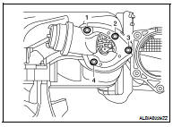
6. If necessary, remove the electric throttle control actuator bolts in the reverse order as shown and remove the electric throttle control actuator.
CAUTION: • Handle carefully to avoid any shock to the electric throttle control actuator.
• Do not disassemble.
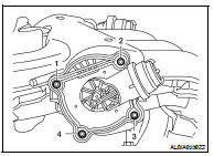
7. If necessary, remove power valve bolts in the reverse order as shown and remove the power valves.
8. Disconnect the following: • Power brake booster vacuum hose
• Coolant hoses from the electric throttle control actuator
• Fuel injector electrical connectors
• PCV hose
• Electric throttle control actuator electrical connector
• EVAP canister purge hose
CAUTION: • Cover any engine openings to avoid the entry of any foreign material.
9. Remove the EVAP canister purge volume solenoid valve bracket bolt. Position the valve aside.
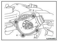
10. Loosen the intake manifold collector bolts in the order as shown using power tool, and remove the intake manifold collector and gasket.
11. If necessary remove the following components: • VIAS control solenoid valve
• EVAP canister purge volume control solenoid valve
INSTALLATION
Installation is in the reverse order of removal.
• Tighten intake manifold collector bolts in the order as shown.
• Tighten power valve bolts in the order shown.
CAUTION: The power valve must be held in the closed position during installation.
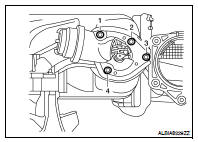
• Tighten electric throttle control actuator bolts in the order shown.
NOTE: After installation, it is necessary to re-calibrate the electric throttle control actuator as follows: 1. Perform the ″Throttle Valve Closed Position Learning″ when harness connector of the electric throttle control actuator is disconnected. Refer to EC-1053, "THROTTLE VALVE CLOSED POSITION LEARNING : Description".
2. Perform the ″Idle Air Volume Learning″ when the electric throttle control actuator is replaced. Refer to EC- 1053, "IDLE AIR VOLUME LEARNING : Description".
 Air cleaner and air duct
 Intake manifold