Nissan Altima (L32) 2007-2012 Service Manual: Parking brake system
PEDAL TYPE
Inspection
• Check control device for wear or other damage. Replace if necessary.
• Check wires for wear or damage. Replace if necessary.
• Check warning lamp and switch. Replace if necessary.
• Check parts at each connecting position and if found deformed or damaged, replace as necessary.
• Check if the parking brake pedal stroke is within specification. Refer to PB-3, "PEDAL TYPE : Adjustment".
Adjustment
ADJUSTMENT
1. Remove rear wheel and tires. Refer to WT-66, "Adjustment".
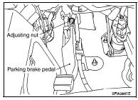
2. Insert a deep socket wrench onto adjusting nut. Rotate adjusting nut to fully loosen cable, and then release parking brake pedal.
3. Secure disc rotor to hub using wheel nut so as not to tilt disc rotor.
4. Remove adjuster hole plug installed on the disc rotor. Turn the adjuster in direction (A) using a suitable tool or a flat-bladed screwdriver as shown, until disc rotor is locked. Turn the adjuster in the opposite direction by 5 or 6 notches after locking.
5. Rotate disc rotor to make sure that there is no drag. Install the adjuster hole plug.
6. Adjust parking brake cable with the following procedure.
a. Operate parking brake pedal 10 or more times with a full stroke of 194.3 mm (7.6 in).
b. Rotate adjusting nut to adjust parking brake pedal stroke using a deep socket wrench.
c. Operate parking brake pedal with a force of 294 N (30 kg-f, 66 lb-f), make sure the pedal stroke is within the specified number of notches. Check it by listening and counting the ratchet clicks.
Pedal stroke (number of notches) : Refer to PB-11, "Parking Brake Control".
d. Make sure that there is no drag on the parking brake with the parking brake pedal completely released.
LEVER TYPE
Inspection
• Check control device for wear or other damage. Replace if necessary.
• Check wires for wear or damage. Replace if necessary.
• Check warning lamp and switch. Replace if necessary.
• Check parts at each connecting position and if found deformed or damaged, replace as necessary.
• Check if the control lever stroke is within specification. Refer to PB-4, "LEVER TYPE : Adjustment".
Adjustment
1. Fully engage the control lever.
2. Loosen the parking brake cable adjusting nut and fully release the control lever.
3. Adjust clearance of the rear parking brake shoes. Refer to PB- 9, "Removal and Installation".
4. Depress the brake pedal fully more than five times.
5. Make sure that no drag exists while rotating the rear wheel and tires.
6. Operate control lever 10 times or more with a full stroke of 99.5 mm (3.9 in).
7. Adjust control lever by turning adjusting nut.
8. Pull control lever with a force of 294 N (30 kg-f, 66 lb-f). Check control lever stroke and ensure smooth operation.
Lever stroke (number of notches) : Refer to PB-11, "Parking Brake Control".
9. After adjustment, check that there is no drag while the control lever is being released. If drag exists, perform the following: • Remove the rear disc rotor. Refer to BR-35, "BRAKE CALIPER ASSEMBLY : Removal and Installation". Verify the toggle lever returns to stopper when the parking brake lever is released.
• If toggle lever does not return to stopper, loosen adjusting nut.
• Install rear disc rotor and adjust shoe clearance. Refer to PB-9, "Removal and Installation".
 On-vehicle maintenance
 Parking brake shoe