Nissan Altima (L32) 2007-2012 Service Manual: ABS branch line circuit
Diagnosis Procedure
INSPECTION PROCEDURE
1.CHECK CONNECTOR
1. Turn the ignition switch OFF.
2. Disconnect the battery cable from the negative terminal.
3. Check the terminals and connectors of the ABS actuator and electric unit (control unit) for damage, bend and loose connection (unit side and connector side).
Is the inspection result normal? YES >> GO TO 2.
NO >> Repair the terminal and connector.
2.CHECK HARNESS FOR OPEN CIRCUIT
1. Disconnect the connector of ABS actuator and electric unit (control unit).
2. Check the resistance between the ABS actuator and electric unit (control unit) harness connector terminals.
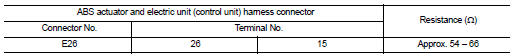
Is the measurement value within the specification? YES >> GO TO 3.
NO >> Repair the ABS actuator and electric unit (control unit) branch line.
3.CHECK POWER SUPPLY AND GROUND CIRCUIT
Check the power supply and the ground circuit of the ABS actuator and electric unit (control unit). Refer to the following.
• Models with ABS: BRC-41, "Wiring Diagram - Coupe" or BRC-46, "Wiring Diagram - Sedan" • Models with TCS: BRC-109, "Wiring Diagram - Coupe" or BRC-115, "Wiring Diagram - Sedan" • Models with VDC: BRC-207, "Wiring Diagram - Coupe" or BRC-215, "Wiring Diagram - Sedan" Is the inspection result normal? YES (Present error)>>Replace the ABS actuator and electric unit (control unit). Refer to the following.
• Models with ABS: BRC-66, "Exploded View" • Models with TCS: BRC-137, "Exploded View" • Models with VDC: BRC-239, "Exploded View" YES (Past error)>>Error was detected in the ABS actuator and electric unit (control unit) branch line.
NO >> Repair the power supply and the ground circuit.
 M&A branch line circuit
 IPDM-E branch line circuit