Nissan Altima (L32) 2007-2012 Service Manual: ASCD Indicator
Description
The ASCD operation status is indicated by two indicators, (CRUISE and SET on the information display) on the combination meter.
CRUISE indicator is displayed to indicate that ASCD system is ready for operation when MAIN switch on ASCD steering switch is turned ON.
SET indicator is displayed when the following conditions are met.
• CRUISE indicator is displayed.
• SET/COAST switch on ASCD steering switch is turned ON while vehicle speed is within the range of ASCD setting.
SET indicator is displayed during ASCD control.
Refer to EC-603, "System Description" for the ASCD function.
Component Function Check
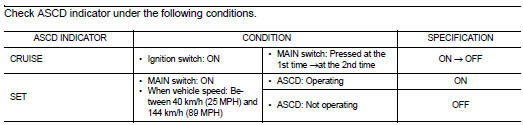
1.ASCD INDICATOR FUNCTION
Is the inspection result normal? YES >> INSPECTION END
NO >> Go to EC-948, "Diagnosis Procedure".
Diagnosis Procedure
1.CHECK DTC
Check that DTC UXXXX is not displayed.
Is the inspection result normal? YES >> GO TO 2.
NO >> Perform trouble diagnosis for DTC UXXXX.
2.CHECK COMBINATION METER OPERATION
Refer to MWI-38, "CONSULT-III Function (METER/M&A)".
Is the inspection result normal? YES >> GO TO 3.
NO >> Check combination meter circuit. Refer to MWI-5, "METER SYSTEM : System Diagram".
3.CHECK INTERMITTENT INCIDENT
Refer to GI-42, "Intermittent Incident".
>> INSPECTION END
 ASCD Brake switch
 Cooling fan