Nissan Altima (L32) 2007-2012 Service Manual: ASCD Indicator
Description
The ASCD operation status is indicated by two indicators, (CRUISE and SET on
the information display) on
the combination meter.
CRUISE indicator is displayed to indicate that ASCD system is ready for
operation when MAIN switch on
ASCD steering switch is turned ON.
SET indicator is displayed when the following conditions are met.
• CRUISE indicator is displayed.
• SET/COAST switch on ASCD steering switch is turned ON while vehicle speed is
within the range of ASCD
setting.
SET indicator is displayed during ASCD control.
Refer to EC-67, "System Description" for the ASCD function.
Component Function Check
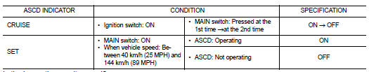
1.ASCD INDICATOR FUNCTION
Check ASCD indicator under the following conditions.
Is the inspection result normal?
YES >> INSPECTION END
NO >> Go to EC-1472, "Diagnosis Procedure".
Diagnosis Procedure
1.CHECK DTC
Check that DTC UXXXX is not displayed.
Is the inspection result normal?
YES >> GO TO 2.
NO >> Perform trouble diagnosis for DTC UXXXX.
2.CHECK COMBINATION METER OPERATION
Refer to MWI-38, "CONSULT-III Function (METER/M&A)".
Is the inspection result normal?
YES >> GO TO 3.
NO >> Check combination meter circuit. Refer to EC-1179, "Diagnosis Procedure".
3.CHECK INTERMITTENT INCIDENT
Refer to GI-42, "Intermittent Incident".
>> INSPECTION END
Description
When the brake pedal is depressed, ASCD brake switch is turned OFF and stop
lamp switch is turned ON.
ECM detects the state of the brake pedal by those two types of input (ON/OFF
s ...
Description
The ECM controls the cooling fan corresponding to the vehicle speed, engine
coolant temperature, refrigerant
pressure, and air conditioner ON signal. The control system has 4-step cont ...
Other materials: Trip computer
1. Vehicle speed
The vehicle speed mode shows the current
vehicle speed and the average vehicle
speed since the last reset.
Average vehicle speed:
Press the OK button on the steering wheel
to bring up the drive computer Reset
menu, and follow the instructions to reset.
For additional information, ...
Vehicle information display warnings
and indicators
The following messages may appear in
your vehicle information display.
Place the key near the start
switch
This indicator appears when the battery of
the Intelligent Key is low and when the Intelligent
Key system and the vehicle are not
communicating normally.
If this appears, touch the ignition s ...
Storage
Front-door pockets
Seatback pockets (if so equipped)
The seatback pockets may be located on
the back of the passenger’s seat. The pockets
can be used to store maps.
WARNING
To ensure proper operation of the driver’s
and/or front passenger's NISSAN Advanced
Air Bag System (if so equipped),
plea ...
 ASCD Brake switch
 Cooling fan