Nissan Altima (L32) 2007-2012 Service Manual: Audio system (sedan)
System Diagram
System Description
AUDIO SYSTEM
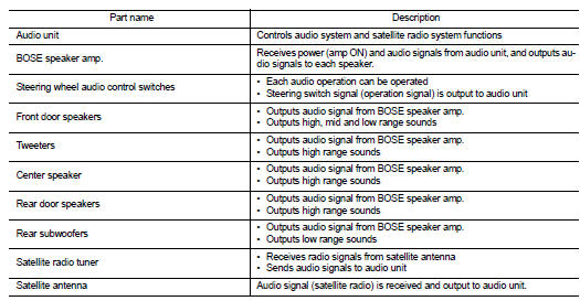
The audio system consists of the following components
• Audio unit
• Window antenna
• BOSE speaker amp.
• Steering wheel audio control switches
• Front door speakers
• Tweeters
• Center speaker
• Rear door speakers
• Rear subwoofers
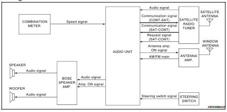
When the audio system is on, radio signals are received by the window antenna. The audio unit then sends audio signals to BOSE speaker amp. The Bose speaker amp. sends the audio signals to the front door speakers, tweeters, center speaker, rear door speakers and rear subwoofers.
Refer to Owner's Manual for audio system operating instructions.
SATELLITE RADIO SYSTEM
The satellite radio system consists of the following components
• Roof antenna (satellite) • Satellite radio tuner
When the satellite radio system is on, radio signals are supplied to the satellite radio tuner from the satellite antenna. The satellite radio tuner then sends audio signals to the audio unit.
Refer to Owner's Manual for satellite radio system operating instructions.
SPEED SENSITIVE VOLUME SYSTEM
Volume level of this system goes up and down automatically in proportion to the vehicle speed. The control level can be selected by the customer. Refer to Owner's Manual for operating instructions.
Component Parts Location
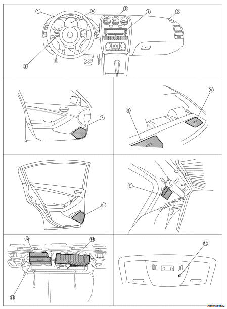
1. Tweeter LH M51
2. Steering wheel audio control switches
3. Tweeter RH M52
4. Audio unit M43, M44, M45, M81
5. Center speaker M151
6. Combination meter M24
7. Front door speaker
LH D3
RH D103
8. Rear subwoofer LH B120
9. Rear subwoofer RH B124
10. Rear door speaker
LH D202
LH D202
11. Antenna amp. M502
12. Satellite radio tuner B123, B129
13. Bluetooth control unit B125, B126
14. BOSE speaker amp. B121, B122
15. Microphone R7
Component Description
 Audio system (coupe)
 Hands free phone system (coupe)