Nissan Altima (L32) 2007-2012 Service Manual: B2108 steering lock relay
Description
The steering lock relay ON signal is transmitted to IPDM E/R by BCM via CAN
communication.
IPDM E/R turns the steering lock relay ON and transmits the release of the
steering to BCM.
DTC Logic
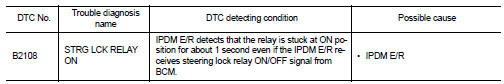
DTC DETECTION LOGIC
NOTE:
• If DTC B2108 is displayed with DTC U1000, first perform the trouble diagnosis
for DTC U1000. Refer to
SEC-433, "DTC Logic".
• If DTC B2108 is displayed with DTC U1010, first perform the trouble diagnosis
for DTC U1010. Refer to
SEC-434, "DTC Logic".
DTC CONFIRMATION PROCEDURE
1.PERFORM DTC CONFIRMATION PROCEDURE
1. Press the push-button ignition switch under the following conditions and
wait for at least 1 second.
- CVT selector lever is in the P position
- Do not depress the brake pedal.
2. Check “Self diagnostic result” with CONSULT-III.
Is DTC detected?
YES >> Refer to SEC-439, "Diagnosis Procedure".
NO >> Inspection End.
Diagnosis Procedure
1.CHECK FUSE
1. Turn ignition switch OFF.
2. Check 10A fuse (No. 40, located in IPDM E/R).
Is the inspection result normal?
YES >> Replace IPDM E/R. Refer to PCS-48, "Removal and Installation".
NO >> Check the following.
• Harness for open or short between IPDM E/R and battery
• Fuse
Description
BCM performs the ID verification with the steering lock unit to release the
steering. BCM starts the communication
with the steering lock unit when keyfob is carried into the passenge ...
Description
The steering lock relay ON signal is transmitted to IPDM E/R by BCM via CAN
communication.
IPDM E/R turns the steering lock relay ON and transmits the release of the
steering to B ...
Other materials: Engine compartment check locations
2.0L 4 cylinder (KR20DDET engine model)
Engine coolant reservoir
Drive belt location
Engine oil filler cap
Brake fluid reservoir
Battery
Fuse/Fusible link box
Air cleaner
Radiator cap
Engine oil dipstick
Windshield-washer fluid reservoir
NOTE:
Your vehicle may not be equipped with
an en ...
ProPILOT Assist system operation
Steering-wheel-mounted control (left)
Vehicle information display
Steering-wheel-mounted control (right)
ProPILOT Assist switch
The ProPILOT Assist system has the following
two functions:
Intelligent Cruise Control (ICC)
The ICC system can be set to one of two
cruise control modes:
Conve ...
Front manual seat adjustment
(if so equipped)
Your vehicle seats can be adjusted manually.
For additional information about adjusting
the seats, refer to the steps outlined
in this section.
WARNING
Before driving the vehicle, return the
seatback to an upright seating position
after manually releasing it. Also, make
sure the seat is locked in p ...
 B2014 chain of strg-immu
 B2109 steering lock relay