Nissan Altima (L32) 2007-2012 Service Manual: B210b starter control relay
Description
Starter control relay, integrated in IPDM E/R, permits the starter relay
operation when in N or P position and
the steering is locked or unlocked. It is installed in parallel with the starter
relay.
DTC Logic
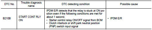
DTC DETECTION LOGIC
NOTE:
• If DTC B210B is displayed with DTC U1000, first perform the trouble diagnosis
for DTC U1000. Refer to
SEC-235, "DTC Logic".
• If DTC B210B is displayed with DTC U1010, first perform the trouble diagnosis
for DTC U1010. Refer to
SEC-236, "DTC Logic".
DTC CONFIRMATION PROCEDURE
1.PERFORM DTC CONFIRMATION PROCEDURE
1. Turn the power supply position to start under the following conditions and
wait for at least 1 second.
- CVT selector lever is in the P or N position.
- Depress the brake pedal
2. Check “Self diagnostic result” with CONSULT-III.
Is DTC detected?
YES >> Refer to SEC-247, "Diagnosis Procedure".
NO >> Inspection End.
Diagnosis Procedure
1.INSPECTION START
1. Turn ignition switch ON.
2. Check “Self diagnostic result” with CONSULT-III.
3. Touch “ERASE”.
4. Perform DTC Confirmation Procedure.
See PCS-45, "DTC Index".
Is the DTC B210B displayed again?
YES >> Replace IPDM E/R. Refer to PCS-48, "Removal and Installation".
Description
There are 2 switches in the electronic steering column lock. IPDM E/R
compares those 2 switches conditions
to judge the present steering status and transmit the result to BCM via CAN ...
Description
Starter control relay, integrated in IPDM E/R, permits the starter relay
operation when in N or P position and
the steering is locked or unlocked. It is installed in parallel with the ...
 B210a steering lock condition switch
 B210C starter control relay