Nissan Altima (L32) 2007-2012 Service Manual: B2553 ignition relay
Description
BCM turns ON the following relays to ignition power supply to each ECU when the ignition switch is turned ON.
• Ignition relay-1 (inside IPDM E/R) • Ignition relay-2 (inside fuse block) • Blower fan motor relay
BCM checks any ignition relay ON request for consistency with the actual ignition relay operation status.
DTC Logic
DTC DETECTION LOGIC

DTC CONFIRMATION PROCEDURE
1. PERFORM DTC CONFIRMATION PROCEDURE
1. Turn ignition switch ON under the following conditions, and wait for at least 2 seconds.
- CVT selector lever is in the P or N position.
- Release brake pedal.
2. Check “Self diagnostic result” with CONSULT-III.
Is DTC detected? YES >> Go to PCS-60, "Diagnosis Procedure".
NO >> Inspection End.
Diagnosis Procedure
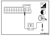
1. CHECK IGNITION RELAY FEEDBACK INPUT SIGNAL
Check voltage between BCM harness connector and ground under the following conditions.


Is the inspection result normal? YES >> Replace BCM. Refer to BCS-96, "Removal and Installation".
NO >> GO TO 2
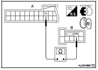
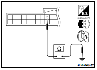
2. CHECK IGNITION RELAY FEEDBACK CIRCUIT
1. Turn ignition switch OFF.
2. Disconnect BCM and fuse block (J/B).
3. Check continuity between BCM harness connector and fuse block harness connector.


4. Check continuity between BCM harness connector and ground.


Is the inspection result normal? YES >> GO TO 3
NO >> Repair or replace harness.
3. CHECK INTERMITTENT INCIDENT
Refer to GI-42, "Intermittent Incident".
>> Inspection End.

 U1010 control unit (CAN)
 B260A ignition relay