Nissan Altima (L32) 2007-2012 Service Manual: B2562 low voltage
DTC Logic
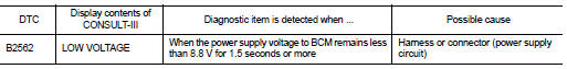
DTC DETECTION LOGIC
DTC CONFIRMATION PROCEDURE
1. DTC CONFIRMATION
1. Erase DTC.
2. Turn ignition switch OFF.
3. Perform the "SELF-DIAG RESULTS" of CONSULT-III, after the ignition switch has
been turned ON for 1.5
seconds or more.
Is any DTC detected?
YES >> Refer to BCS-41, "Diagnosis Procedure".
NO >> Inspection End.
Diagnosis Procedure
1. CHECK BATTERY VOLTAGE
Check battery voltage.
Is battery voltage less than 8.8V?
Yes >> Charge battery and retest. Refer to PG-72, "Work Flow".
No >> GO TO 2
2. CHECK POWER SUPPLY CIRCUIT
Check BCM power supply circuit. Refer to BCS-42, "Diagnosis Procedure".
Is the circuit OK?
Yes >> Replace BCM. Refer to BCS-96, "Removal and Installation".
No >> Repair or replace the malfunctioning part.
Special Repair Requirement
1. REQUIRED WORK WHEN REPLACING BCM
Initialize control unit. Refer to BCS-6, "CONFIGURATION (BCM) : Special
Repair Requirement".
>> Work End.
Description
U0415 is displayed if any unusual condition is present in the reception
status of the vehicle speed signal from
the ABS actuator and electric unit (control unit).
DTC Logic
DTC DET ...
Diagnosis Procedure
1. CHECK FUSE AND FUSIBLE LINK
Check if the following BCM fuse or fusible link are blown.
Is the fuse or fusible link blown?
YES >> Replace the blown fuse or fusible li ...
Other materials: Bluetooth connections screen
"" (back) key
Bluetooth tab
Connections screen
"Add New" key
"" (settings) key
"" (info) key
"" (Bluetooth Audio
connection) key
"" (Bluetooth Hands-Free
Phone System connection) key
Access the Connections screen to change
settings and view Bluetooth information.
To access the Connec ...
Tire chains
CAUTION
Only certain SAE class "S" tire chains
can be used on this vehicle. Using the
wrong Class "S" chains on this vehicle
will cause damage to the vehicle. If you
plan to use tire chains/cables, you
should use a tire chain that meets the
minimum clearances for your vehicle.
Use of tire chains ma ...
Vehicle information display warnings
and indicators
The following messages may appear in
your vehicle information display.
Engine start operation for
Intelligent Key system (if
I-Key battery level is low)
This indicator appears when the battery of
the Intelligent Key is low and when the Intelligent
Key system and the vehicle are not
communicating no ...
 U0415 vehicle speed sig
 Power supply and ground circuit