Nissan Altima (L32) 2007-2012 Service Manual: Clutch disc and clutch cover
Exploded View
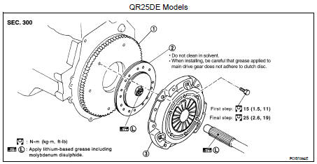
1. Flywheel
2. Clutch disc
3. Clutch cover
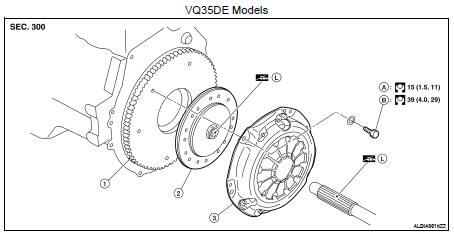
1. Flywheel
2. Clutch disc *1, *2
3. Clutch cover
A. First step
B. Final Step
 Apply lithium-based grease
including molybdenum disulphide
Apply lithium-based grease
including molybdenum disulphide
*1. Do not clean in solvent. *2. When installing, be careful that grease applied to input shaft does not adhere to clutch disc.
Removal and Installation
CAUTION: • If transaxle assembly is removed from the vehicle, always replace CSC (Concentric Slave Cylinder).
Return CSC insert to original position to remove transaxle assembly. Dust on clutch disc sliding parts may damage CSC seal and may cause clutch fluid leakage.
• Be careful not to apply any grease to the clutch disc facing, pressure plate surface and flywheel surface.
• If flywheel is removed, align dowel pin with the smallest hole of flywheel (for VQ35DE engine models).
Refer to EM-206, "Disassembly and Assembly".
• Replace clutch disc and clutch cover as a set (for VQ35DE engine models).
REMOVAL
1. Remove transaxle assembly from the vehicle. Refer to TM-26, "Removal and Installation".
2. Loosen clutch cover bolts evenly. Then remove clutch cover and clutch disc.
INSTALLATION
1. Clean clutch disc and input shaft splines to remove grease and dust caused by abrasion.
2. Apply recommended grease to clutch disc and input shaft splines.
CAUTION: Be sure to apply grease to the points specified. Otherwise, noise, poor disengagement, or damage to the clutch may result. Excessive grease may cause slip or shudder. If it adheres to CSC seal, it will cause clutch fluid leakage. Wipe off excess grease.
3. Install clutch disc using Tool.

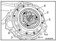
4. Install clutch cover. Pre-tighten clutch cover bolts.
5. Tighten clutch cover bolts evenly in two steps in the order shown. Refer to CL-14, "Exploded View".
6. Install transaxle assembly. Refer to TM-26, "Removal and Installation".
Inspection
CLUTCH DISC
• Measure clutch disc runout and backlash. If either measurement exceeds the specification, replace clutch disc (for QR25DE engine models) or clutch disc and clutch cover as a set (for VQ35DE engine models).

• Check clutch disc for burns, discoloration or oil or grease leakage. Replace if necessary.
• Determine the clutch facing wear limit (depth to the rivet head). If measurement exceeds specifications, replace clutch disc (for QR25DE engine models) or clutch disc and clutch cover as a set (for VQ35DE engine models).

CLUTCH COVER
• Check clutch cover installed on vehicle for unevenness of diaphragm spring toe height. If unevenness exceeds specifications, adjust the height using Tool (A).
• Check clutch cover thrust ring for wear or breakage. If wear or breakage is found, replace clutch cover (for QR25DE engine models) or clutch disc and clutch cover as a set (for VQ35DE engine models).
NOTE: • Worn thrust ring will generate a beating noise when tapped at the rivet using suitable tool.
• Broken thrust ring will make a clinking sound when cover is shaken up and down.
• If a trace of burn or discoloration is found on clutch cover pressure plate to clutch disc contact surface, repair the surface with sandpaper. If surface is damaged or distorted, replace clutch cover (for QR25DE engine models) or clutch disc and clutch cover as a set (for VQ35DE engine models).
 CSC (Concentric slave cylinder)
 Service data and specifications
(SDS)
Service data and specifications
(SDS)