Nissan Altima (L32) 2007-2012 Service Manual: Combination switch output circuit
Diagnosis Procedure
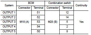
1. CHECK OUTPUT 1 - 5 SYSTEM CIRCUIT FOR OPEN
1. Turn the ignition switch OFF.
2. Disconnect the BCM and combination switch.
3. Check continuity between BCM harness connector and combination
switch harness connector.
Does continuity exist?
YES >> GO TO 2
NO >> Repair or replace harness.
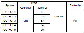
2. CHECK OUTPUT 1 - 5 SYSTEM CIRCUIT FOR SHORT
Check for continuity between BCM harness connector and ground.
Does continuity exist?
YES >> Repair or replace harness.
NO >> GO TO 3
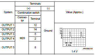
3. CHECK COMBINATION SWITCH OUTPUT VOLTAGE
1. Connect the BCM and combination switch.
2. Turn ON any switch in the system that is malfunctioning.
3. Check voltage between combination switch harness connector
and ground.
Is the measurement normal when any of the switches is turned ON?
YES >> Replace BCM. Refer to BCS-96, "Removal and Installation".
NO >> Replace the combination switch. Refer to WW-121, "Removal and
Installation".
Special Repair Requirement
1. REQUIRED WORK WHEN REPLACING BCM
Initialize control unit. Refer to BCS-6, "CONFIGURATION (BCM) : Special
Repair Requirement".
>> Work End.
Diagnosis Procedure
1. CHECK INPUT 1 - 5 SYSTEM CIRCUIT FOR OPEN
1. Turn the ignition switch OFF.
2. Disconnect the BCM and combination switch.
3. Check continuity between BCM harness connect ...
BCM (BODY CONTROL MODULE)
Reference Value
VALUES ON THE DIAGNOSIS TOOL
Terminal Layout
Physical Values
1: Sedan only
2: With LH front window a ...
Other materials: Sun visors
To block glare from the front, swing
down the main sun visor 1.
To block glare from the side, remove the
main sun visor 2 from the center
mount and swing the visor to the side.
To extend the sun visor, slide in or out as
needed 3.
CAUTION
Do not store the sun visor before returning ...
LDW system limitations
WARNING
Listed below are the system limitations
for the LDW system. Failure to follow
the warnings and instructions for
proper use of the LDW system could result
in serious injury or death.
The system will not operate at
speeds below approximately 37 mph
(60 km/h) or if it cannot detect lane
ma ...
Forward-facing child restraint
installation using LATCH
For additional information, see all Warnings
and Cautions in "Child safety" and
"Child restraints" before installing a
child restraint.
Do not use the lower anchors if the combined
weight of the child and the child restraint
exceeds 65 lbs. (29.5 kg). If the combined
weight of the child and the chi ...
 Combination switch input circuit
 ECU diagnosis