Nissan Altima (L32) 2007-2012 Service Manual: Consult-iii checking system
Description
• When CONSULT-III is connected with a data link connector
equipped on the vehicle side, it will communicate with the control
unit equipped in the vehicle and then enable various kinds of diagnostic
tests.
1 : Hood release handle
2 : Data link connector
• Refer to “CONSULT-III Operation Manual” for more information.
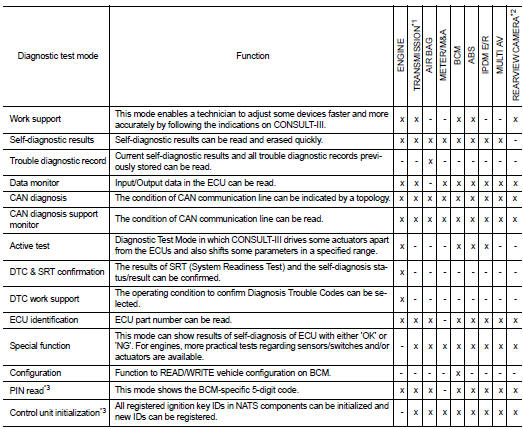
Function and System Application
x: Applicable
*1: With continuously variable transmission
*2: With NAVI
*3: With security card installed
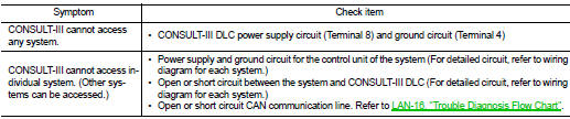
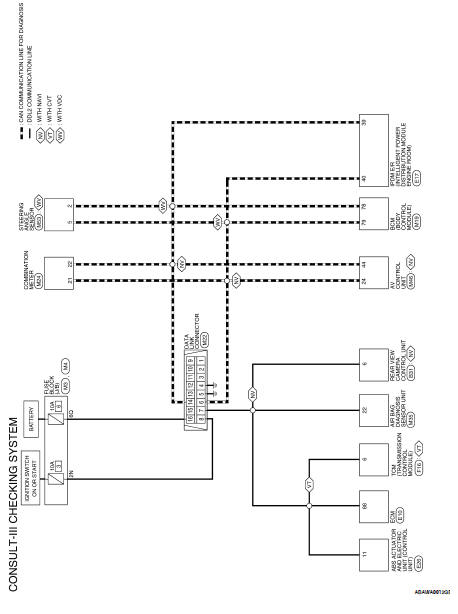
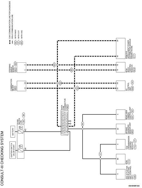
CONSULT-III Data Link Connector (DLC) Circuit
INSPECTION PROCEDURE
If the CONSULT-III cannot diagnose the system properly, check the
following items.
NOTE:
The DDL2 circuits and CAN communication lines from DLC pins 6, 7 and 14 may be
connected to more than
one system. A short in a DDL circuit or CAN lines connected to a control unit in
one system may affect CONSULT-
III access to other systems. For a complete DDL circuit layout, refer to GI-52,
"Wiring Diagram - Coupe"
or GI-53, "Wiring Diagram - Sedan". For a complete CAN line layout, refer to
LAN-29, "Wiring Diagram - CAN
SYSTEM -".
Work Flow
Control Units and Electrical Parts
PRECAUTIONS
• Never reverse polarity of battery terminals.
• Install only parts specified for a vehicle.
• Before replacing the control ...
 Service information for electrical
incident
Service information for electrical
incident Engine mechanical