Nissan Altima (L32) 2007-2012 Service Manual: Control system
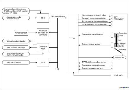
System Diagram
System Description
The CVT senses vehicle operating conditions through various sensors. It
always controls the optimum shift
position and reduces shifting and lock-up shocks.
CONTROL SYSTEM OUTLINE
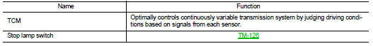
The function of the TCM is to:
• Receive input signals sent from various switches and sensors.
• Determine required line pressure, shifting point, and lock-up operation.
• Send required output signals to the step motor and the respective solenoids.
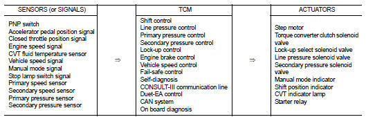
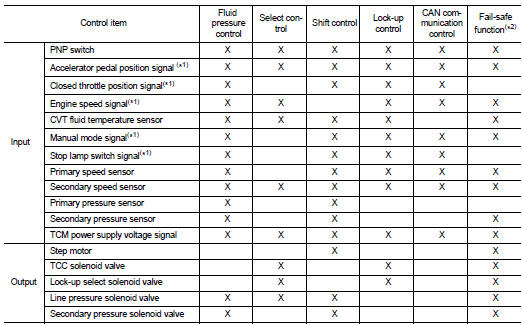
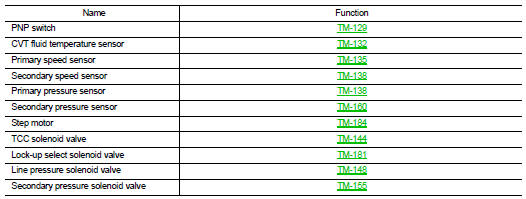
INPUT/OUTPUT SIGNAL OF TCM
*1: Input by CAN communications.
*2: If these input and output signals are different, the TCM triggers the
fail-safe function.
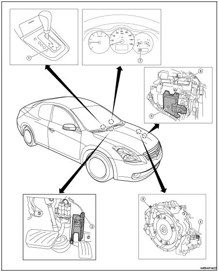
Component Parts Location - Coupe
1. Control device assembly (Manual
mode select switch and manual
mode position select switch)
2. Accelerator pedal position (APP)
sensor
3. Secondary speed sensor
4. CVT unit harness connector
5. TCM
6. Battery
7. Shift position indicator
Manual mode indicator
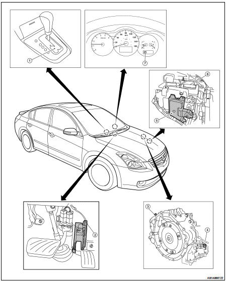
Component Parts Location - Sedan
1. Control device assembly (Manual
mode select switch and manual
mode position select switch)
System Diagram
System Description
The hydraulic control mechanism consists of the oil pump directly driven by
the engine, the hydraulic control
valve that controls line pressure and transmissi ...
System Diagram
System Description
• The torque converter clutch piston in the torque converter is engaged to
eliminate torque converter slip to
increase power transmission efficiency.
• ...
 Hydraulic control system
 Lock-up and select control system