Nissan Altima (L32) 2007-2012 Service Manual: Cylinder block
Disassembly and Assembly
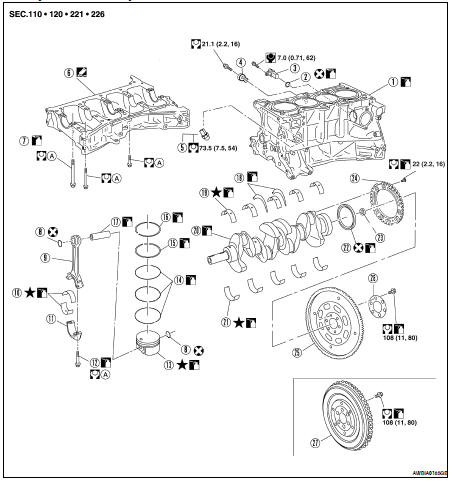
1. Cylinder block
2. O-ring
3. Crankshaft position sensor (POS)
4. Knock sensor
5. Cylinder block heater (if equipped)
6. Lower cylinder block
7. Lower cylinder block bolt
8. Snap ring
9. Connecting rod
10. Connecting rod bearing
11. Connecting rod bearing cap
12. Connecting rod bearing cap bolt
13. Piston
14. Oil ring
15. Second ring
16. Top ring
17. Piston pin
18. Main thrust bearing
19. Main bearing upper
20. Crankshaft
21. Main bearing lower
22. Crankshaft rear oil seal
23. Pilot converter (CVT)
24. Crankshaft signal plate
25. Drive plate (CVT)
26. Reinforcement plate (CVT)
27. Flywheel (M/T)
A. Follow assembly procedure
CAUTION: Apply new engine oil to parts marked in illustration before installation.
DISASSEMBLY
1. Remove the engine and transaxle as an assembly from the vehicle, and separate the transaxle from the engine. Refer to EM-72, "Removal and Installation".
2. Mount the engine on a suitable engine stand.
3. Drain any remaining engine oil and coolant from the engine.
4. Remove the following components and associated parts.
• Exhaust manifold and three way catalyst assembly. Refer to EM-30, "Removal and Installation".
• Intake manifold collector. Refer to EM-26, "Removal and Installation".
• Intake manifold and fuel tube assembly. Refer to EM-26, "Removal and Installation".
• Ignition coils. Refer to EM-35, "Removal and Installation".
• Rocker cover. Refer to EM-39, "Removal and Installation".
• Front cover, timing chain, and balancer unit. Refer to EM-52, "Removal and Installation".
• Cylinder head. Refer to EM-64, "Removal and Installation".
5. Remove the knock sensor.
CAUTION: Carefully handle the sensor and do not drop the sensor.
6. Remove crankshaft position sensor (POS).
CAUTION: • Avoid impacts such as a dropping.
• Do not disassemble.
• Keep it away from metal particles.
• Do not place sensor close to magnetic materials.
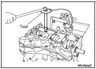
7. Remove the flywheel (M/T models) or drive plate (CVT models).
Hold the crankshaft with a stopper plate and use a suitable tool to remove the bolts.
CAUTION: • Be careful not to damage the flywheel contact surface for the clutch disc.
NOTE: • The flywheel two-block construction allows movement in response to transmission side pressure, or when twisted in its rotational direction, therefore, some amount of noise is normal.
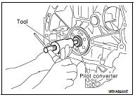
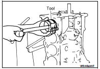
8. Remove pilot converter using Tool (CVT models).
Tool Number : ST16610001 (J-23907)
9. Remove the piston and connecting rod assemblies.
a. Position the crankshaft and corresponding connecting rod, to be removed, to the bottom dead center stroke.
b. Remove the connecting rod cap. Number the cap so it can be assembled in the same position.
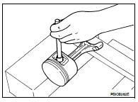
c. Using a hammer handle or similar tool, push the piston and connecting rod assembly out of the top of the cylinder block. Number the piston and rod so it can be assembled in the same position.
• Before removing the piston and connecting rod assembly, check the connecting rod side clearance.
Refer to EM-83, "Inspection After Disassembly".
10. Remove the connecting rod bearings. If reusing, number them so they can be assembled in the same position and direction.
CAUTION: • When removing them, note the installation position. Keep them in the correct order.
11. Remove the piston rings from the piston.
• Use a piston ring expander.
• Before removing the piston rings, check the piston ring side clearance. Refer to EM-83, "Inspection After Disassembly".
CAUTION: • When removing the piston rings, be careful not to damage the piston.
• Be careful not to damage piston rings by expanding them excessively, if reusing them.
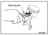
12. Remove the piston from the connecting rod as follows.
a. Using a snap ring pliers, remove the two snap rings.
b. Heat the piston to 60° - 70°C (140° - 158°F) with a heat gun, or equivalent.
c. Push out piston pin with a punch of an outer diameter of approximately 19 mm (0.75 in).
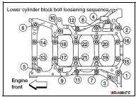
13. Remove the lower cylinder block bolts.
• Before loosening the lower cylinder block bolts, measure the crankshaft side clearance. Refer to EM-83, "Inspection After Disassembly".
• Loosen them in the order as shown to remove them.
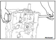
14. Remove the lower cylinder block.
• Cut the Silicone RTV Sealant and remove the lower cylinder block from the cylinder block, using Tool.
Seal cutter KV10111100 (J-37228)
CAUTION: Be careful not to damage the mating surface.
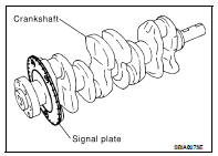
15. Remove the crankshaft.
CAUTION: • Do not damage or deform the signal plate while mounted on the crankshaft.
• When setting the crankshaft on a flat surface, use a block of wood to avoid interference between the signal plate and the surface.
• Do not remove signal plate unless it is necessary.
16. Pull the rear oil seal out of the rear end of the crankshaft.
CAUTION: Do not to damage the crankshaft or cylinder block when removing the rear oil seal.
NOTE: When replacing the rear oil seal without removing the cylinder block, use a screwdriver to pull it out from between crankshaft and block.
17. Remove the main bearings and thrust bearings from the cylinder block and lower cylinder block.
CAUTION: Identify and number the bearings, if reusing them, so that they are assembled in the same position and direction.
ASSEMBLY
1. Using compressed air, clean out the coolant and oil passages in the cylinder block, the cylinder bore and the crankcase to remove any foreign material.
WARNING: Use approved safety glasses to protect your eyes.
2. Install the drain plugs on the cylinder block.
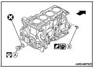
• Apply Silicone RTV Sealant.
Use Genuine Silicone RTV Sealant, or equivalent. Refer to GI-15, "Recommended Chemical Products and Sealants".
• Replace the copper washers with new ones.
•  : Front
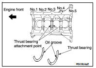
3. Install the main bearings and the thrust bearings.
a. Remove dust, dirt, and oil from the bearing mating surfaces of the cylinder block and lower cylinder block.
b. Install the thrust bearings to both sides of the No. 3 main bearing journal on the cylinder block.
• Install the thrust bearings with the oil groove facing the crankshaft arm (outside).
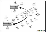
c. Install the main bearings paying attention to their position and direction.
• The main bearing with an oil hole and groove goes on the cylinder block side (A). The one without them goes on the lower cylinder block side (B).
• Only the main bearing (on the cylinder block side) for No. 3 journal (6) has different specifications.
• Before installing the bearings, apply engine oil to the bearing friction surface (inside). Do not apply oil to the back surface, but thoroughly clean it.
• When installing, align the bearing stopper (1), (5) to the notch.
• Make sure that the oil holes on the cylinder block and those on the corresponding bearing (2), (4) are aligned.
(3) : Journal other than No. 3 (7) : Thrust bearings
4. Install the signal plate to the crankshaft.
a. Position the crankshaft and signal plate using a positioning dowel pin, and tighten the bolts to specification.
b. Remove the dowel pin.
CAUTION: Be sure to remove dowel pin before installing the crankshaft.
NOTE: Dowel pins for the crankshaft and signal plate are supplied as a set for each.
5. Install the crankshaft onto the cylinder block.
• While turning the crankshaft by hand, check that it turns smoothly.
6. Install the lower cylinder block.
• Apply Silicone RTV Sealant to positions as shown.
• Use Genuine Silicone RTV Sealant, or equivalent. Refer to GI- 15, "Recommended Chemical Products and Sealants".
CAUTION: After the Silicone RTV Sealant is applied, the lower cylinder block installation must be finished within 5 minutes.
NOTE: Cylinder block and lower cylinder block are machined together. Neither of them can be replaced separately.
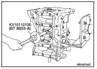
7. Tighten lower cylinder block bolts in the numerical order as shown and according to the following steps:
CAUTION: Check tightening angle. Do not make judgment by visual inspection.
Tool number : KV 10112100 (BT-8653-A)
a. Apply new engine oil to threads and seat surfaces of the bolts.
b. Tighten bolts No. 11 - 22 only in the order as shown, to specification below.
Step 1, bolts 11 - 22 only : 25.1 N·m (2.6 kg-m, 19 ft-lb)
c. Tighten bolts No. 1 - 10 only in the order as shown, to specification below.
Step 2, bolts 1 - 10 only : 39.2 N·m (4.0 kg-m, 29 ft-lb)
d. Tighten bolts No. 1 - 10 only in the order as shown, to specification below.
Step 3, bolts 1 - 10 only : 60°degrees rotation
• Wipe off completely any protruding Silicone RTV Sealant on rear oil seal installation surface and the exterior of engine.
• Check crankshaft side clearance. Refer to EM-83, "Inspection After Disassembly".
• After installing the bolts, make sure that the crankshaft can be rotated smoothly by hand.
8. Install the rear oil seal.
• Press the oil seal between cylinder block and crankshaft with a suitable drift.
• Be careful not to touch the grease on the oil seal lip.
• Be careful not to cause scratches or burrs when pressing in the rear oil seal.
• Press in rear oil seal to the position as shown.
9. Install the piston to the connecting rod. Assemble the components in their original positions.
a. Using a snap ring pliers, install the snap ring to the grooves of the piston's rear side.
• Insert the piston pin snap ring fully into groove.
b. Install the piston to the connecting rod.
• Using a heat gun, heat the piston [approximately 60° - 70 C° (140° - 158 °F)] until the piston pin can be pushed in by hand without excessive force. From the front to the rear, insert the piston pin into the piston and the connecting rod.
• Assemble so that the front mark on the piston crown and the oil holes and the cylinder No. on the connecting rod are positioned as shown.
c. Install the piston pin snap ring into the front of the piston.
• Check that the connecting rod moves smoothly.
10. Using a piston ring expander, install the piston rings. Assemble the components in their original positions.
CAUTION: Be careful not to damage the piston.
• Position each ring with the gap as shown, referencing the piston front mark as the starting point.
• Install the top ring and the second ring with the stamped surface facing upward.
11. Install the connecting rod bearings to the connecting rod and the connecting rod cap. Assemble the components in their original positions.
• When installing the connecting rod bearings, apply engine oil to the bearing friction surface (inside). Do not apply oil to the back surface, but thoroughly clean the back.
• When installing, align the connecting rod bearing stopper protrusion with the notch of the connecting rod to install.
• Check the oil holes on the connecting rod and those on the corresponding bearing are aligned.
12. Install the piston and connecting rod assembly using Tool.
Assemble the components in their original positions.
Tool number : EM03470000 (J-8037)
• Rotate the crankshaft so the pin corresponding to the connecting rod to be installed is at the bottom dead center position.
• Apply engine oil sufficiently to the cylinder bore, piston, and crankshaft pin.
• Match the cylinder position number with the cylinder No. on the connecting rod for installation.
• Install the piston with the front mark on the piston crown facing the front of the engine using Tool.
CAUTION: Be careful not to damage the crankshaft pin, resulting from an interference of the connecting rod big end.
13. Install the connecting rod caps. Assemble the components in their original positions.
• Match the stamped cylinder number marks on the connecting rod with those on the cap to install.
14. Tighten the connecting rod bolts using Tool as follows: Apply engine oil to the threads and seats of the connecting rod bolts.
CAUTION: Check tightening angle. Do not make judgment by visual inspection.
• Check the connecting rod side clearance. Refer to EM-83, "Inspection After Disassembly".
• After tightening the bolts, make sure that the crankshaft rotates smoothly.
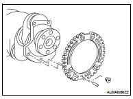
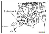
15. Install flywheel (M/T Models), or drive plate (CVT Models).
• Install drive plate, reinforcement plate and pilot converter as shown.
• Using a drift with 33 mm (1.30 in) diameter, push pilot converter into the end of the crankshaft.
16. Install the knock sensor.
• Make sure that there is no foreign material on the cylinder block mating surface and the back surface of the knock sensor.
• Install the knock sensor with the connector facing lower left by 45° as shown.
• Do not tighten the bolts while holding the connector.
• Make sure that the knock sensor does not interfere with other parts.
CAUTION: If the knock sensor is dropped, replace it with new one.
17. Install the crankshaft position sensor (POS).
18. Installation of remaining components is in the reverse order of removal.
Inspection After Disassembly
CRANKSHAFT SIDE CLEARANCE
• Using a dial gauge, measure the clearance between the thrust bearings and the crankshaft arm when the crankshaft is moved fully forward or backward.
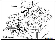
• If the measured value exceeds the limit, replace the thrust bearings, and measure again. If it still exceeds the limit, replace the crankshaft.
CONNECTING ROD SIDE CLEARANCE
• Measure side clearance between connecting rod and crankshaft arm using a feeler gauge.
• If the measured value exceeds the limit, replace the connecting rod bearings, and measure again. If it still exceeds the limit, replace the crankshaft also.
PISTON AND PISTON PIN CLEARANCE
Diameter of Piston Pin Bore
• Measure the diameter of piston pin bore using an inside micrometer.
Refer to EM-99, "Standard and Limit".
Outer Diameter of Piston Pin
• Measure outer diameter of piston pin using a micrometer. Refer to EM-99, "Standard and Limit".
Piston to Piston Pin Clearance
(Piston pin clearance) = (Piston pin bore diameter) – (Outer diameter of piston pin) • A: Front mark
• B: Piston pin bore grade
• C: Piston grade I.D. stamp
• D: Piston crown I.D. code stamp
Standard : 0.002 - 0.006 mm (0.0001 - 0.0002 in)
• If clearance exceeds specification, replace either or both of piston/ piston pin assembly and connecting rod assembly with reference to specification of each parts.
• Use the piston selection table to replace piston/piston pin assembly.
Refer to EM-93, "How to Select Piston and Bearing".
• Use the connecting rod bearing selection table to replace connecting rod. Refer to EM-93, "How to Select Piston and Bearing".
NOTE: • The connecting rod small end grade and piston pin hole (piston pin) grade are provided only for the parts installed at the plant. For service parts, no grades can be selected. Only 0 grade is available.
• Follow the "CONNECTING ROD BUSHING OIL CLEARANCE (SMALL END)" procedure for the values for each grade at the plant.
PISTON RING SIDE CLEARANCE
• Measure side clearance of piston ring and piston ring groove using a feeler gauge. Refer to EM-99, "Standard and Limit".
• If out of specification, replace piston and/or piston ring assembly.
PISTON RING END GAP
• Check if inner diameter of cylinder bore is within specification.
Follow the "PISTON TO CYLINDER BORE CLEARANCE" procedure.
• Insert piston ring until middle of cylinder with piston, and measure gap using a feeler gauge. Refer to EM-99, "Standard and Limit".
• If out of specification, replace piston ring.
CONNECTING ROD BEND AND TORSION
• Check with connecting rod aligner. Refer to EM-99, "Standard and Limit".

• If it exceeds the limit, replace connecting rod assembly.
CONNECTING ROD BEARING (BIG END)
• Install the connecting rod cap without the connecting rod bearing installed. After tightening the connecting rod bolt to the specified torque, measure the connecting rod big end inner diameter using an inside micrometer. Refer to EM-99, "Standard and Limit".
CONNECTING ROD BUSHING OIL CLEARANCE (SMALL END)
Inner Diameter of Connecting Rod (Small End)
• Measure inner diameter of bushing. Refer to EM-99, "Standard and Limit"
Outer Diameter of Piston Pin
• Measure outer diameter of piston pin. Refer to EM-99, "Standard and Limit".
Piston Pin to Connecting Rod Bushing Clearance (Small End) (Piston pin to connecting rod bushing clearance (small end)) = (Inner diameter of connecting rod small end) – (Outer diameter of piston pin)
Standard : 0.005 - 0.017 mm (0.0002 - 0.0007 in)
• If the measured value exceeds the standard, replace the connecting rod assembly and/or piston and piston pin assembly.
• If replacing the piston and piston pin assembly, use the "Piston Selection Table" to select the piston corresponding to the applicable bore grade of the cylinder block to be used. Refer to EM-93, "How to Select Piston and Bearing".
Factory Installed Parts Grading: • Service parts apply only to grade 0 (B).
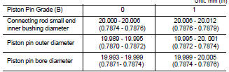
• A: Front mark
• C: Piston grade I.D. stamp
• D: Piston crown I.D. code stamp
CYLINDER BLOCK DISTORTION
• Using a scraper, remove gasket on the cylinder block surface, and also remove oil, scale, carbon, or other contamination.
CAUTION: Be careful not to allow gasket debris to enter the oil or coolant passages.
• Measure the distortion on the block upper face at some different points in 6 directions.
Limit : 0.1 mm (0.004 in)
• If out of the distortion limit, replace the cylinder block and lower block they are machined together as an assembly.
INNER DIAMETER OF MAIN BEARING HOUSING
• Install the main bearing caps with the main bearings removed and tighten the bolts to the specified torque. Refer to EM-76, "Disassembly and Assembly".
• Using a bore gauge, measure the inner diameter of the main bearing housing.
Standard : 58.944 - 58.968 mm (2.3206 - 2.3216 in)
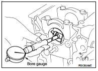
• If out of the standard, replace the cylinder block and lower cylinder block assembly.
NOTE: These components cannot be replaced as a single unit because they were processed together.
PISTON TO CYLINDER BORE CLEARANCE
Inner Diameter of Cylinder Bore
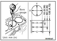
• Using a bore gauge, measure cylinder bore for wear, out-of-round and taper at 6 different points on each cylinder. (X and Y directions at A, B and C). The Y axis is in the longitudinal direction of the engine.
NOTE: When determining cylinder bore grade, measure cylinder bore at B position. Refer to EM-99, "Standard and Limit".
• If there are scratches and/or seizure on the cylinder inner wall, hone the inner wall.
Outer Diameter of Piston
• Measure piston skirt diameter using a micrometer. Refer to EM-99, "Standard and Limit".
• Measure point (distance from the top): 37.5 mm (1.476 in)
Piston to Cylinder Bore Clearance
• Calculate by outer diameter of piston skirt and inner diameter of cylinder (direction X, position B).
(Clearance) = (Inner diameter of cylinder) – (Outer diameter of piston skirt).
• If it exceeds the limit, replace piston/piston pin assembly.
Reboring Cylinder Bore
1. Cylinder bore size is determined by adding piston-to-bore clearance to piston diameter “A”.
Rebored size calculation: D = A + B - C
D: Bored diameter
A: Piston diameter as measured
B: Piston-to-bore clearance (standard value)
C: Honing allowance 0.02 mm (0.0008 in)
2. Install lower cylinder block, and tighten to the specified torque. Otherwise, cylinder bores may be distorted in final assembly.
3. Cut cylinder bores.
• When any cylinder needs boring, all other cylinders must also be bored.
• Do not cut too much out of cylinder bore at a time. Cut only 0.05 mm (0.0020 in) or so in diameter at a time.
4. Hone cylinders to obtain specified piston-to-bore clearance.
5. Measure finished cylinder bore for out-of-round and taper.
• Measurement should be done after cylinder bore cools down.
OUTER DIAMETER OF CRANKSHAFT JOURNAL
• Measure outer diameter of crankshaft journals.
Standard : 54.955 - 54.979 mm (2.1636 - 2.1645 in)
OUTER DIAMETER OF CRANKSHAFT PIN
• Measure outer diameter of crankshaft pin.
Standard : 44.956 - 44.974 mm (1.7699 - 1.7706 in)
OUT-OF-ROUND AND TAPER OF CRANKSHAFT
• Measure the dimensions at four different points as shown on each journal and pin using a micrometer.
• Out-of-round is indicated by the difference in dimensions between (X) and (Y) at (A) and (B).
• Taper is indicated by the difference in dimension between (A) and (B) at (X) and (Y).
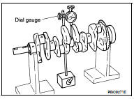
CRANKSHAFT RUNOUT
• Place a V-block on a precise flat table to support the journals on both ends of the crankshaft.
• Place a dial gauge straight up on the No. 3 journal.
• While rotating the crankshaft, read the movement of the pointer on the dial gauge, the total indicator runout reading.
Limit : Less than 0.05 mm (0.002 in)
OIL CLEARANCE OF CONNECTING ROD BEARING
Method of Measurement
• Install the connecting rod bearings to the connecting rod and the cap, and tighten the connecting rod bolts to the specified torque.
Using a inside micrometer measure the inner diameter of connecting rod bearing.
(Oil clearance) = (Inner diameter of connecting rod bearing) – (Outer diameter of crankshaft pin)

• If clearance cannot be adjusted within the standard, grind crankshaft pin and use undersized bearing. Refer to EM-93, "How to Select Piston and Bearing".
Method of Using Plastigage
• Remove oil and dust on the crankshaft pin and the surfaces of each bearing completely.
• Cut the Plastigage slightly shorter than the bearing width, and place it in crankshaft axial direction, avoiding oil holes.
• Install the connecting rod bearings to the connecting rod cap, and tighten the connecting rod bolts to the specified torque.
CAUTION: Never rotate the crankshaft.
• Remove the connecting rod cap and bearings, and using the scale on the Plastigage bag, measure the Plastigage width.
NOTE: The procedure when the measured value exceeds the limit is same as that described in the method by calculation.
OIL CLEARANCE OF MAIN BEARING
Method of Measurement
• Install the main bearings to the cylinder block and bearing cap. Measure the main bearing inner diameter with the bearing cap bolt tightened to the specified torque.
(Oil clearance) = (Inner diameter of main bearing) – (Outer diameter of crankshaft journal)
If the measured value exceeds the limit, select main bearings referring to the main bearing inner diameter and crankshaft journal outer diameter, so that the oil clearance satisfies the standard. Refer to EM-93, "How to Select Piston and Bearing".
Method of Using Plastigage
• Remove oil and dust on the crankshaft journal and the surfaces of each bearing completely.
• Cut the Plastigage slightly shorter than the bearing width, and place it in crankshaft axial direction, avoiding oil holes.
• Tighten the main bearing bolts to the specified torque.
CAUTION: Never rotate the crankshaft.
• Remove the bearing cap and bearings, and using the scale on the plastigage bag, measure the plastigage width.
NOTE: The procedure when the measured value exceeds the limit is same as that described in the "Method by Calculation".
CRUSH HEIGHT OF MAIN BEARING
• When the bearing cap is removed after being tightened to the specified torque with main bearings installed, the tip end of bearing must protrude.
Standard : There must be crush height.
• If the standard is not met, replace main bearings.
OUTER DIAMETER OF LOWER CYLINDER BLOCK BOLT
• Perform only with M10 (0.39 in) bolts.
• Measure outer diameters (d1, d2) at two positions as shown.
• Measure d2 at a point within area (A) as shown.
• When the value of d1- d2 exceeds the limit (a large difference in dimensions), replace the bolt with a new one.
Limit : 0.13 mm (0.0051 in)
OUTER DIAMETER OF CONNECTING ROD BOLT
• Measure outer diameter (d) at position as shown.
• When (d) exceeds the limit (when it becomes thinner), replace the bolt with a new one.
Limit : 7.75 mm (0.3051 in) or less
MOVEMENT AMOUNT OF FLYWHEEL (M/T MODEL) NOTE:
• Inspection for double mass flywheel only.
• Do not disassemble double mass flywheel.
Flywheel Deflection
• Measure deflection of flywheel contact surface to the clutch with a dial gauge.
• Measure runout at 210 mm (8.27 in) dia.

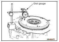
• Measure axial displacement at 250 mm (9.84 in) dia.

• When measured value exceeds the limit, replace the flywheel with a new one.
Movement Amount in Rotation Direction
• Check the movement amount in the following procedure.
1. Install a bolt to clutch cover mounting hole, and place a torque wrench on the extended line of the flywheel center line.
• Tighten bolt to keep it from loosening at a force of 9.8 N·m (1 kg-m, 87 in-lb).
2. Put a mating mark on circumferences of the two flywheel masses without applying any load (measurement standard points).
3. Apply a force of 9.8 N·m (1 kg-m, 87 in-lb) in each direction, and mark the movement amount on the mass on the transmission side.
4. Measure dimensions of movement amounts (A) and (B) on circumference of the flywheel on the transmission side.
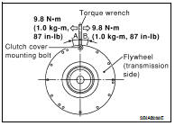
Standard : 35 mm (1.38 in) or less
• When measured value is outside the standard, replace flywheel.
 Disassembly and assembly
 How to select piston and bearing