Nissan Altima (L32) 2007-2012 Service Manual: Diagnosis sensor unit
Removal and Installation
REMOVAL
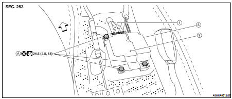
1. Diagnosis sensor unit harness connector
2. Diagnosis sensor unit shield
3. Diagnosis sensor unit
A. Diagnosis sensor unit bolts

CAUTION: • Before servicing, turn ignition switch OFF, disconnect both battery terminals and wait at least three minutes.
• Before disconnecting the air bag sensor unit harness connector, be sure to disconnect the harness connector of each air bag module and pre-tensioner seat belt to prevent air bag deployment by static electricity.
• Do not use air tools or electric tools for servicing.
• Do not use old bolts after removal; replace with new bolts.
• Do not cause an impact to the diagnosis sensor unit by dropping etc. Replace the diagnosis sensor unit if it has been dropped or sustained an impact.
• Replace the diagnosis sensor unit of deployed SRS air bag and deployed SRS front seat belt pre-tensioner.
1. Disconnect the negative and positive battery terminals, then wait at least three minutes.
2. Disconnect connector of each air bag module and seat belt pre-tensioner. Refer to SR-5, "Removal and Installation", SR-10, "Removal and Installation", SR-12, "Removal and Installation", SE-23, "Removal and Installation", SB-8, "Removal and Installation".
3. Remove the center console. Refer to IP-18, "Disassembly and Assembly".
4. Disconnect the diagnosis sensor unit harness connectors.
5. Remove the bolts, then remove the diagnosis sensor unit.
INSTALLATION
Installation is in the reverse order of removal.
CAUTION: • Be careful not to damage the diagnosis sensor unit harness.
• After the work is completed, make sure no system malfunction is detected by air bag warning lamp.
• In case a malfunction is detected by the air bag warning lamp, reset by the self-diagnosis function and delete the memory by CONSULT−lIl.
• If a malfunction is still detected after the above operation, perform self-diagnosis to repair malfunctions.
Refer to SRC-12, "SRS Operation Check".
ECU DISCRIMINATED NO.
After replacing the diagnosis sensor unit, confirm that the diagnosis sensor unit identification is correct for the vehicle as equipped. Refer to SRC-14, "CONSULT-III Function (AIR BAG)".
 Side air bag (satellite) sensor
 Occupant classification system
control unit
Occupant classification system
control unit