Nissan Altima (L32) 2007-2012 Service Manual: Disassembly and assembly
FRONT DRIVE SHAFT
Disassembly and Assembly (Left Side)
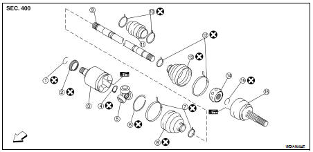
1. Circlip
2. Dust shield
3. Slide joint housing
4. Snap ring
5. Spider assembly
6. Stopper ring
7. Boot band
8. Boot
9. Shaft
10. Damper band
11. Damper
12. Boot band
13. Boot
14. Ball cage / Steel ball / Inner race assembly
15. Circlip
16. Joint sub-assembly

DISASSEMBLY
Transaxle Side
1. Mount front drive shaft in a vise.
CAUTION: When mounting shaft in a vise, always use copper or aluminum plates between vise and shaft. 2. Remove boot bands and slide the boot back.
3. Remove circlip and dust shield from slide joint housing.
4. Put matching marks on slide joint housing and shaft before separating joint assembly.
5. Remove stopper ring with a suitable tool, then pull out slide joint housing.
6. Put matching marks on spider assembly and shaft.
7. Remove snap ring using a suitable tool, then remove spider assembly from shaft.
8. Remove boot from shaft.
9. Clean the old grease off of the slide joint assembly.
Wheel Side
1. Mount the front drive shaft in a vise.
CAUTION: When mounting shaft in a vise, always use copper or aluminum plates between vise and shaft. 2. Remove boot bands and slide the boot back.
3. Screw a sliding hammer or suitable tool 30 mm (1.18 in) or more into threaded part of joint sub-assembly. Pull joint sub-assembly out of shaft.
CAUTION: • Align sliding hammer or suitable tool and drive shaft then remove joint sub-assembly by pulling directly.
• If joint sub-assembly cannot be removed after five or more unsuccessful attempts, replace the entire drive shaft assembly.
4. Remove boot from shaft.
5. Remove circlip from shaft.
6. While rotating ball cage, clean the old grease off of the joint sub-assembly.
Damper
• Remove damper bands, then remove damper from shaft.
INSPECTION AFTER DISASSEMBLY
Shaft
• Replace shaft if there is bending, cracking, or other damage.
Joint Sub-Assembly
• Make sure there is no rough rotation or unusual axial looseness.
• Make sure there is no foreign material inside joint sub-assembly.
• Check joint sub-assembly for compression scars, cracks or fractures.
CAUTION: If there are any irregular conditions of joint sub-assembly components, replace the entire joint subassembly.
Slide Joint Housing
• Make sure there are no compression scars, cracks or fractures or unusual wear of ball rolling surface.
• Make sure there is no damage to shaft screws.
• Make sure there is no deformation of boot installation parts.
Ball Cage
• Make sure there are no compression scars, cracks, fractures of sliding surface.
Steel Ball
• Make sure there are no compression scars, cracks, fractures or unusual wear.
Inner Race
• Check ball sliding surface for compression scars, cracks or fractures.
• Make sure there is no damage to serrated part.
CAUTION: If there are any irregular conditions in the component, replace with a new set of joint sub-assembly, ball cage, steel ball and inner race.
Damper
• Check damper for cracks or wear. Install damper with new damper bands.
ASSEMBLY
Transaxle Side
1. Install new boot and new small boot band on shaft.
CAUTION: • Cover drive shaft serration with tape to prevent damage to boot during installation. 2. Remove protective tape wound around serrated part of shaft.
3. Install spider assembly securely, making sure the matching marks which were made during disassembly are properly aligned.
4. Install new snap ring using a suitable tool.
5. Pack drive shaft with specified amount of new grease (Genuine NISSAN Grease or equivalent).
Grease amount : 134 – 144 g (4.73 – 5.08 oz)
6. Install new stopper ring to housing of slide joint assembly.
7. After installation, pull shaft to check engagement between slide joint assembly and stopper ring.
8. Install boot securely into grooves (indicated by * marks) as shown.
CAUTION: If there is grease on boot mounting surfaces (indicated by * marks) of shaft and housing, boot may come off. Clean all grease from surfaces. 9. Make sure boot installation length (L) is the length specified below. Insert a flat-bladed screwdriver or similar tool into the large end of boot. Bleed air from boot to prevent boot deformation.
Boot installation length (L) : 167.9 mm (6.61 in)
CAUTION: • Boot may break if boot installation length is less than standard value.
• Be careful that screwdriver tip does not contact inside surface of boot. 10. Secure large and small ends of boot with new boot bands as shown.
CAUTION: Discard old boot bands and replace with new ones.

11. Install new dust shield to slide joint housing.
12. After installing housing and shaft, make sure boot position is correct. If boot position is not correct, remove old boot bands then reposition the boot and secure with new boot bands.
Wheel Side
1. Insert the amount of grease (Genuine NISSAN Grease or equivalent) into joint sub-assembly serration hole until grease begins to ooze from ball groove and serration hole. After inserting grease, use a shop cloth to wipe off old grease that has oozed out.
2. Cover serrated part of shaft with tape. Install new boot band and boot to shaft. Be careful not to damage boot.
CAUTION: Discard old boot band and boot; replace with new one. 3. Remove protective tape wound around serrated part of shaft.
4. Attach new circlip to shaft. The circlip must fit securely into shaft groove. Attach nut to joint sub-assembly.
Use a suitable tool to press-fit.
CAUTION: Discard old circlip and replace with new one.
5. Insert the amount of new grease (Genuine NISSAN Grease or equivalent) listed below into housing from large end of boot.
Grease amount : 170 – 190 g (6.00 – 6.70 oz)
6. Install boot securely into grooves (indicated by * marks) as shown.
CAUTION: If there is grease on boot mounting surfaces (indicated by * marks) of shaft and housing, boot may come off. Remove all grease from surfaces. 7. Make sure boot installation length (L) is the specified length indicated below. Insert a flat-bladed screwdriver or similar tool into the large end of boot. Bleed air from boot to prevent boot deformation.
Boot installation length (L) : 163 mm (6.42 in)
CAUTION: • Boot may break if boot installation length is less than standard value.
• Be careful that screwdriver tip does not contact inside surface of boot.
8. Install new large and small boot bands securely using Tool.
Tool number : KV40107300 ( — )
NOTE: Do not reuse boot bands.
CAUTION: • Secure boot band so that dimension (M) meets specification as shown.
Dimension (M) : 1.0 – 4.0 mm (0.039 – 0.157 in)

9. After installing housing and shaft, rotate boot to check whether or not the actual position is correct. If boot position is not correct, remove old boot bands then reposition the boot and secure with new boot bands.
Damper
1. Use new damper bands for installation.
2. Install damper from stationary-joint side while holding it securely.

Disassembly and Assembly (Right Side)
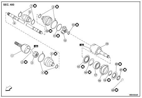
1. Joint sub-assembly
2. Circlip
3. Ball cage / Steel ball / Inner race assembly
4. Boot bands
5. Boot
6. Shaft
7. Damper bands
8. Damper
9. Boot band
10. Boot
11. Stopper ring
12 Spider assembly
13. Snap ring
14. Slide joint housing
15. Dust cover
16. Snap ring
17. Bearing
18. Retaining bracket (QR25DE engine)
19. Snap ring
20. Dust shield
21. Dust shield
22. Circlip

DISASSEMBLY
Transaxle Side
1. Press shaft in a vise.
CAUTION: When retaining shaft in a vise, always use copper or aluminum plates between vise and shaft. 2. Remove circlip and dust shield from slide joint housing.
3. Remove boot bands and slide the boots back.
4. Put matching marks on slide joint housing and shaft before separating slide joint housing.
5. Remove stopper ring using a suitable tool, then pull out slide joint housing.
6. Put matching marks on spider assembly and shaft.
7. Remove snap ring using a suitable tool, then remove spider assembly from shaft.
8. Remove boot from shaft.
9. Clean old grease off of the slide joint housing.
Wheel Side
1. Mount the front drive shaft in a vise.
CAUTION: When mounting shaft in a vise, always use copper or aluminum plates between vise and shaft. 2. Remove boot bands and slide the boot back.
3. Screw a sliding hammer or suitable tool 30 mm (1.18 in) or more into threaded part of joint sub-assembly. Pull joint sub-assembly out of shaft.
CAUTION: • Align sliding hammer or suitable tool and drive shaft then remove joint sub-assembly by pulling directly.
• If joint sub-assembly cannot be removed after five or more unsuccessful attempts, replace the entire drive shaft assembly.
4. Remove boot from shaft.
5. Remove circlip from shaft.
6. While rotating ball cage, clean the old grease off of the joint sub-assembly.
Support Bearing
1. Remove dust shield from slide joint assembly using a suitable tool.
2. Remove snap ring using a suitable tool.

3. Press support bearing assembly off slide joint assembly using a suitable tool.
4. With QR25DE engine, separate support bearing from retaining bracket using a suitable tool.
Damper
• Remove damper bands, then remove damper from shaft.
INSPECTION AFTER DISASSEMBLY
Shaft
• Replace shaft if there is any bending, cracking, or other damage.
Joint Sub-assembly
• Make sure there is no rough rotation or unusual axial looseness.
• Make sure there is no foreign material inside joint sub-assembly.
• Check joint sub-assembly for compression scars, cracks or fractures.
CAUTION:
If there are any irregular conditions of joint sub-assembly components, replace the entire joint subassembly.
Sliding Joint Housing and Spider Assembly
• If roller surface of spider assembly has scratches or wear, replace housing and spider assembly.
NOTE: Housing and spider assembly are components which are used as a set.
Support Bearing
• Make sure wheel bearing rolls freely and is free from noise, cracks, pitting or wear.
Damper
• Check damper for cracks or wear. Install damper with new damper bands.
ASSEMBLY
Transaxle Side
1. Cover serrated part of shaft with tape. Install new boot and boot band onto shaft. Be careful not to damage boot.
CAUTION: • Discard old boot and boot band; replace with new ones.
2. Remove protective tape wound around serrated part of shaft.
3. Install spider assembly securely, making sure the matching marks which were made during disassembly are properly aligned.
4. Install new snap ring using a suitable tool.
5. Pack drive shaft with specified amount of grease (Genuine NISSAN Grease or equivalent).
Grease amount : 134 - 144 g (4.73 - 5.08 oz)
6. Install new stopper ring to slide joint assembly.
7. After installation, pull shaft to check engagement between slide joint assembly and stopper ring.
8. Install boot securely into grooves (indicated by * marks) as shown.
CAUTION: If there is grease on boot mounting surfaces (indicated by * marks) of shaft and housing, boot may come off. Remove all grease from surfaces. 9. Make sure boot installation length (L) is the length indicated below. Insert a flat-bladed screwdriver or similar tool into the large end of boot. Bleed air from boot to prevent boot deformation.
Boot installation length (L) : 189.30 mm (7.45 in)
CAUTION: • Boot may break if boot installation length is less than standard value.
• Be careful that screwdriver tip does not contact inside surface of boot.
10. Secure big and small ends of boot with new boot bands as shown.
CAUTION: Discard old boot bands; replace with new ones. 11. Install new dust shield to slide joint housing.
12. After installing housing and shaft, rotate boot to check whether or not the actual position is correct. If boot position is not correct, remove old boot bands then reposition the boot and secure with new boot bands.
Wheel Side
1. Insert the amount of grease (Genuine NISSAN Grease or equivalent) into joint sub-assembly serration hole until grease begins to ooze from ball groove and serration hole. After inserting grease, use a shop cloth to wipe off old grease that has oozed out.
2. Cover serrated part of shaft with tape. Install new boot and boot band onto shaft. Be careful not to damage boot.
CAUTION: Discard old boot and boot band; replace with new ones. 3. Remove protective tape wound around serrated part of shaft.
4. Attach new circlip to shaft. The circlip must fit securely into shaft groove. Attach nut to joint sub-assembly.
Use a suitable tool to press-fit.
CAUTION: Discard old circlip; replace with new ones.
5. Insert the amount of new grease (Genuine NISSAN Grease or equivalent) listed below into housing from large end of boot.
Grease amount : 170 – 190 g (6.00 – 6.70 oz)
6. Install boot securely into grooves (indicated by * marks) as shown.
CAUTION: If there is grease on boot mounting surfaces (indicated by * marks) of shaft and housing, boot may come off. Remove all grease from surfaces. 7. Make sure boot installation length (L) is the specified length.
Insert a flat-bladed screwdriver or similar tool into the large end of boot. Bleed air from boot to prevent boot deformation.
Boot installation length (L) : 163 mm (6.42 in)
CAUTION: • Boot may break if boot installation length is less than standard value.
• Be careful that screwdriver tip does not contact inside surface of boot.
8. Install new large and small boot bands securely using Tool.
Tool number : KV40107300 ( — )
NOTE: Do not reuse boot bands.
CAUTION: • Secure boot band so that dimension (M) meets specification as shown.
Dimension (M) : 1.0 – 4.0 mm (0.039 – 0.157 in)
9. After installing housing and shaft, rotate boot to check whether or not the actual position is correct. If boot position is not correct, remove old boot bands then reposition the boot and secure with new boot bands.
Support Bearing
1. With QR25DE engine, press support bearing into retaining bracket using a suitable tool.
2. Install support bearing onto slide joint assembly.
3. Install snap ring.
4. Install dust shield.
Damper
1. Use new damper bands for installation.
2. Install damper from stationary-joint side while holding it securely.

 Front drive shaft
 Service data and specifications
(SDS)
Service data and specifications
(SDS)