Nissan Altima (L32) 2007-2012 Service Manual: Disassembly and assembly
DOOR MIRROR
Exploded View
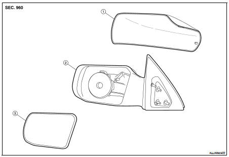
1. Door mirror cover
2. Mirror housing assembly
3. Mirror glass and holder
Disassembly
1. Turn the mirror glass surface upward.
2. Apply a protective tape (A) to mirror housing. Insert a suitable tool (B) into the concave gap between the mirror holder (1) and mirror motor (2) Push up tabs (3) (two locations) on the mirror holder to disengage the lower part of mirror holder, and remove the mirror glass and holder.
NOTE: When pushing up tabs (3), do not forcefully push up only one concave position but try to push up two concave positions.
3. Remove the mirror glass and holder (1) from the mirror housing assembly (2).
4. Disconnect the two terminals from the mirror heater connector (if equipped).
Assembly
1. Place mirror glass and holder and mirror housing assembly (actuator) in a horizontal position.
2. Connect the two terminals to the mirror heater connector (if equipped).
3. Engage the upper tabs on the mirror glass and holder (1) onto the mirror motor (2) Then press the lower side of mirror face until a click sound is heard to engage the lower tabs.
NOTE: After installation, visually make sure lower two tabs are securely engaged from the bottom of mirror face.
Make sure to insert the harness terminals into the correct connector.
Do not confuse the locations.
DOOR MIRROR COVER
Disassembly
1. Using a suitable tool disengage the upper mirror cover pawls.

2. Using a suitable tool disengage the lower mirror cover pawls and remove mirror cover.
CAUTION: Be careful not to damage the mirror or mirror cover with tool.
Assembly
Installation is in the reverse order of removal.
CAUTION: After installation, check that pawls are securely engaged.
 Door mirror
 Exterior lighting system