Nissan Altima (L32) 2007-2012 Service Manual: Door switch
Description
Detects door open/close condition and transmits the signal to BCM.
Component Function Check
1. CHECK DOOR SWITCH INPUT SIGNAL
Check (“DOOR SW-DR” and “DOOR SW-AS”) in “DATA MONITOR” mode with CONSULT-III. Refer to BCS- 34, "RETAINED PWR : CONSULT-III Function (BCM - RETAINED PWR)".
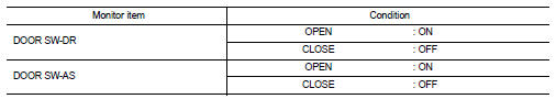
Is the inspection result normal? YES >> Door switch circuit is OK.
NO >> Refer to PWC-32, "Diagnosis Procedure".
Diagnosis Procedure
1. CHECK HARNESS CONTINUITY
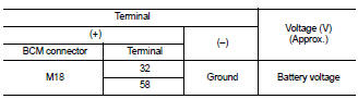
Check voltage between BCM connector and ground.
Is the measurement value within the specification? YES >> Replace BCM. Refer to BCS-96, "Removal and Installation".
NO >> GO TO 2
2. CHECK HARNESS CONTINUITY
1. Turn ignition switch OFF.
2. Disconnect BCM and door switch.
3. Check continuity between BCM connector (A) and door switch connector (B).
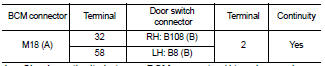
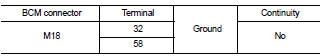
4. Check continuity between BCM connector (A) and ground.
Is the inspection result normal? YES >> GO TO 3
NO >> Repair or replace harness.
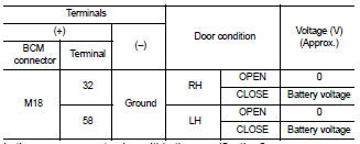
3. CHECK BCM OUTPUT SIGNAL
1. Connect BCM connector.
2. Check voltage between BCM connector and ground.
Is the measurement value within the specification? YES >> GO TO 4
NO >> Replace BCM. Refer to BCS-96, "Removal and Installation".
4. CHECK DOOR SWITCH
Check front door switch.
Refer to PWC-33, "Component Inspection".
Is the inspection result normal? YES >> Check intermittent incident. Refer to GI-42, "Intermittent Incident".
NO >> Replace door switch.
Component Inspection
1. CHECK DOOR SWITCH
Check front door switches.
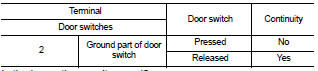
Is the inspection result normal? YES >> Door switch is OK.
NO >> Replace door switch.
 Encoder
 Power window lock switch