Nissan Altima (L32) 2007-2012 Service Manual: ECM branch line circuit
Diagnosis Procedure
INSPECTION PROCEDURE
1.CHECK CONNECTOR
1. Turn the ignition switch OFF.
2. Disconnect the battery cable from the negative terminal.
3. Check the following terminals and connectors for damage, bend and loose connection (unit side and connector side).
- ECM
- Harness connector E30
- Harness connector M1
Is the inspection result normal? YES >> GO TO 2.
NO >> Repair the terminal and connector.
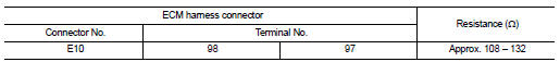
2.CHECK HARNESS FOR OPEN CIRCUIT
1. Disconnect the connector of ECM.
2. Check the resistance between the ECM harness connector terminals.
Is the measurement value within the specification? YES >> GO TO 3.
NO >> Repair the ECM branch line.
3.CHECK POWER SUPPLY AND GROUND CIRCUIT
Check the power supply and the ground circuit of the ECM. Refer to the following.
• QR engine models for California: EC-144, "Diagnosis Procedure" • QR engine models expect for California: EC-673, "Diagnosis Procedure" • VQ engine models: EC-1175, "Diagnosis Procedure" Is the inspection result normal? YES (Present error)>>Replace the ECM. Refer to the following.
• QR engine models for California: EC-27, "ADDITIONAL SERVICE WHEN REPLACING CONTROL UNIT : Special Repair Requirement" • QR engine models except for California: EC-563, "ADDITIONAL SERVICE WHEN REPLACING CONTROL UNIT : Special Repair Requirement" • VQ engine models: EC-1051, "ADDITIONAL SERVICE WHEN REPLACING CONTROL UNIT : Special Repair Requirement" YES (Past error)>>Error was detected in the ECM branch line.
NO >> Repair the power supply and the ground circuit.
 Main line between dlc and abs circuit
 A-BAG branch line circuit