Nissan Altima (L32) 2007-2012 Service Manual: Evaporative emission system
System Diagram
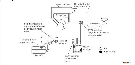
EVAPORATIVE EMISSION LINE DRAWING
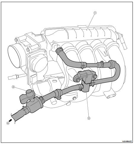
1. Intake manifold collector
2. EVAP service port
3. EVAP canister purge volume control solenoid valve
A. From next figure
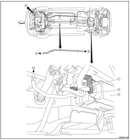
1. EVAP control system pressure sensor
2. EVAP canister vent control valve
3. EVAP canister
A. To previous figure
NOTE: Do not use soapy water or any type of solvent while installing vacuum hose or purge hoses.
System Description
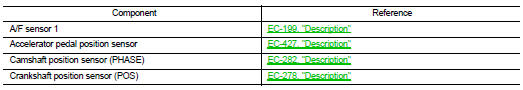
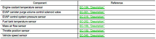
INPUT/OUTPUT SIGNAL CHART
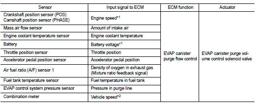
*1: ECM determines the start signal status by the signals of engine speed and battery voltage.
*2: This signal is sent to the ECM through CAN communication line.
SYSTEM DESCRIPTION
The evaporative emission system is used to reduce hydrocarbons emitted into the atmosphere from the fuel system. This reduction of hydrocarbons is accomplished by activated charcoals in the EVAP canister.
The fuel vapor in the sealed fuel tank is led into the EVAP canister which contains activated carbon and the vapor is stored there when the engine is not operating or when refueling to the fuel tank.
The vapor in the EVAP canister is purged by the air through the purge line to the intake manifold when the engine is operating. EVAP canister purge volume control solenoid valve is controlled by ECM. When the engine operates, the flow rate of vapor controlled by EVAP canister purge volume control solenoid valve is proportionally regulated as the air flow increases.
EVAP canister purge volume control solenoid valve also shuts off the vapor purge line during decelerating.
Component Parts Location
1. Intake valve timing control solenoid valve
2. Ignition coil (with power transistor) and spark plug
3. Knock sensor, Crankshaft position sensor (POS)
4. Air fuel ratio (A/F) sensor 1
5. Camshaft position sensor (PHASE)
6. Engine coolant temperature sensor
7. Park/neutral position (PNP) switch
8. ECM
9. Refrigerant pressure sensor
10. Battery current sensor
11. IPDM E/R
12. Mass air flow sensor (with intake temperature sensor)
13. Tumble control valve actuator
14. EVAP service port
15. Electric throttle control actuator (with built in throttle position sensor and throttle control motor)
16. EVAP canister purge volume control solenoid valve
17. Fuel injector
18. Power steering pressure sensor
1. Battery
2. Fuel pump fuse (15A)
3. IPDM E/R
4. Brake master cylinder
5. Engine ground
6. Air cleaner assembly
7. Mass air flow sensor (with intake air temperature sensor)
8. Radiator hose (upper)
9. Engine coolant temperature sensor
10. Intake air duct
11. Camshaft position sensor (PHASE)
12. Tie rod (RH)
13. Power steering pressure sensor
14. Knock sensor
15. Engine oil cooler
16. Crankshaft position sensor (POS)
17. Drive shaft (RH)
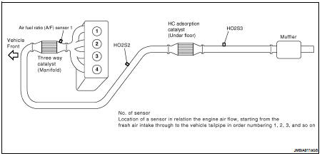
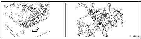
1. Exhaust manifold cover
2. Air fuel ratio (A/F) sensor 1
3. Heated oxygen sensor 2 (This illustration is a view from under vehicle.)
4. Engine oil pan
1. EVAP service port
2. Intake air duct
3. EVAP canister purge volume control solenoid valve
4. Intake manifold collector
5. Park/neutral position (PNP) switch (CVT) (This illustration is view with air cleaner assembly removed.)
6. Park/neutral position (PNP) switch (M/T) (This illustration is view with air cleaner assembly removed.)
7. Intake valve timing control solenoid valve (This illustration is view with engine removed.)
8. Exhaust manifold cover
9. Air fuel ratio (A/F) sensor 1
10. Air fuel ratio (A/F) sensor 1 harness connector
11. Heated oxygen sensor 2 (This illustration is view from under vehicle.)
12. Heated oxygen sensor 2 harness connector (This illustration is view from under vehicle.)
13. Engine oil pan
14. Heated oxygen sensor 3 (This illustration is view form under vehicle.)
15. Heated oxygen sensor 3 harness connector (This illustration is view from under vehicle.)
1. Thermostat housing
2. Tumble control valve actuator
3. Throttle valve (This illustration is view with intake air duct removed.)
4. Electric throttle control actuator
5. Fuel injector harness connector
6. Condenser-2
7. Radiator hose (upper)
8. Battery
9. ECM
10. Fuel level sensor unit and fuel pump harness connector (This illustration is view with rear seat cushion and inspection hole cover removed.)
11. Fuel level sensor unit and fuel pump assembly
12. Fuel pressure regulator
13. Fuel tank temperature sensor
14. EVAP control system pressure sensor (This illustration is view with rear suspension member removed.)
15. EVAP canister vent control valve (This illustration is view with rear suspension member removed.)
16. EVAP canister (This illustration is view with rear suspension member removed.)
1. No.1 ignition coil
2. Cooling fan motor-1 harness connector
3. Cooling fan motor-2 harness connector
4. Refrigerant pressure sensor
5. Accelerator pedal position sensor
6. ASCD brake switch
7. Stop lamp switch
8. Brake pedal
9. ASCD clutch switch
10. Clutch pedal
11. ASCD steering switch
12. CANSEC switch
13. RESUME/ACCELERATE switch
14. SET/COAST switch
15. MAIN switch
Component Description
 Cooling fan control
 Intake valve timing control