Nissan Altima (L32) 2007-2012 Service Manual: Front bumper
Removal and Installation
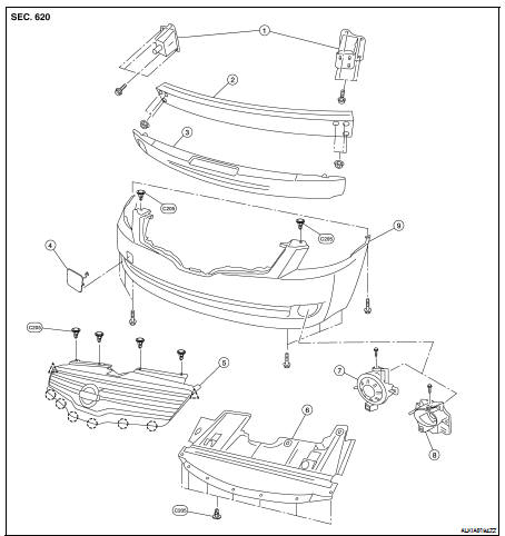
1. Front bumper supports
2. Front bumper reinforcement
3. Energy absorbing foam
4. Tow cover
5. Front grille
6. Engine under cover
7. Fog lamp finisher (if equipped)
8. Fog lamp (if equipped)
9. Front bumper fascia


REMOVAL
1. Remove the front fender protectors RH and LH. Refer to EXT-40, "Removal
and Installation".
2. Remove the engine under cover.
3. Remove the front grille. Refer to EXT-38, "Removal and Installation".
4. Remove the fog lamp if equipped. Refer to EXL-256, "Removal and
Installation".
5. Remove the front bumper fascia clips and screws, then remove the front
bumper fascia.
6. Remove the front energy absorbing foam.
7. Remove the front bumper reinforcement.
8. Remove the front bumper supports.
INSTALLATION
Installation is in the reverse order of removal.
Removal and Installation
1. Rear bumper supports
2. Rear bumper reinforcement
3. Energy absorbing foam
4. Splash shield LH
5. Rear bumper fascia
6. Splash shield RH
REMOVAL
1. Remove the L ...
 On-vehicle repair
 Rear bumper